
Technical data


7 Verifying SPI Serial Bus Communication
40 Agilent InfiniiVision 7000B Series Oscilloscopes Evaluation Guide
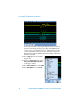
7 Press [Serial]; then, select the SPI
decode mode.
8 Press Signals; then, select the D1 as
the Clock source.
9 Press Data; then, select D3 as the
serial data signal source.
10 Press ~CS; then, select D0 as the Chip
Select (not) source.
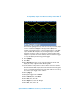
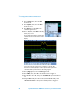
You should now be able to view the SPI
serial decode trace at the bottom of the
display.
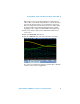
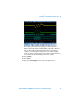
Let’s now set up the oscilloscope to trigger on a specific SPI
transmission of data (02 10) in order to synchronize acquisitions
coincident with a specific burst of the analog signals.
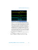
11 Press [Trigger]; then, select the SPI trigger mode.
12 Press #Bits; then, select 16 as the number of bits to trigger on.
13 Press 0 1 X to select “0”; then, press Set all Bits 0 to preset all 16 bits to
“0”.
14 Using the Bit softkey, the selection knob, and the 0 1 X softkey, enter
“000 0010 0001 0000” as the specific serial bit pattern to trigger on.