
Technical data


39
Agilent InfiniiVision 7000B Series Oscilloscopes
Evaluation Guide
7
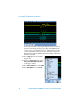
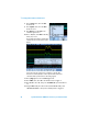
Verifying SPI Serial Bus
Communication
Another common serial bus protocol used in many embedded designs is the
Serial Peripheral Interface (SPI) bus. Although this bus requires more signals
than the I
2
C bus, it is a very flexible serial bus protocol that the designer can
define, such as customizing the number of bits in each serial transmission.
While the I
2
C bus is primarily used for chip-to-chip communication within a
single PC board, the SPI bus can be used for chip-to-chip communication or
for serial communication to nearby peripherals. To enable SPI decoding, your
oscilloscope must have the low speed serial bus decode option (Option LSS)
installed. You can verify the installed options on your oscilloscope at [Utility]
> Service > About Oscilloscope.
Setup
1 Connect the demo kit’s 40-pin ribbon cable from the back of the Agilent
InfiniiVision Series oscilloscope to the 40-pin connector on the demo
board.
2 Connect channel 1 probe to the CH1 test point and ground (GND).
3 Connect channel 2 probe to the CH2 test point and ground (GND).
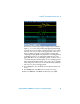
4 Set the rotary switch on the demo board for the SPI signal (Mode #6).
5 Press [Default Setup].
6 Press [Auto Scale].