
Technical data


Verifying I
2
C Serial Bus Communication 6
Agilent InfiniiVision 7000B Series Oscilloscopes Evaluation Guide 35
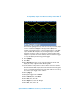
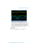
Notice that the oscilloscope may trigger on multiple chirps of different
lengths (1, 2, or 3 cycles) using standard edge triggering (default trigger
mode after Auto Scale). To trigger on the first chirp that consists of three
sine wave cycles, we can set up the I
2
C triggering of the oscilloscope to
trigger on a Write cycle based on a specific address and serial data
content. Digital signals D7-D0 are the digital inputs to the DAC generated
by the MCU. D15 is the I
2
C clock signal (SCL) and D14 is the I
2
C data
signal (SDA). Before we set up the trigger condition, we will first turn on
I
2
C serial decoding. Note that although the I
2
C clock and data signals are
being captured by the digital channels of the oscilloscope, I
2
C triggering
and decoding on the oscilloscope can also utilize the analog channels as
input sources for the clock and data signals.
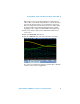
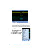
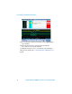
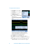
8 Press [Serial]; then, select the I
2
C decode mode (default serial decode
mode).
9 Press Settings; then, select D15 as the clock input source (SCL).
10 Next, press SDA; then, select D14 as the data input source (SDA).