
Technical data


34
Agilent InfiniiVision 7000B Series Oscilloscopes
Evaluation Guide
6
Verifying I
2
C Serial Bus
Communication
Many of today’s embedded designs include serial bus communications using
protocols such as I
2
C (Inter-Integrated Circuit). The I
2
C bus is primarily used
for chip-to-chip communications. In this lab you will see that the I
2
C bus
generates a series of commands to instruct the microcontroller to generate
three specific chirps (or bursts) with a varying numbers of pulses. Our goal is
to synchronize the oscilloscope’s display on specific chirps using the
oscilloscope’s I
2
C trigger capabilities and verify the serial data
transmissions. To enable I
2
C decoding, your oscilloscope must have the
low-speed serial bus decode option (Option LSS) installed. You can verify the
installed options on your oscilloscope at [Utility] > Service > About
Oscilloscope.
Setup
1 Connect the demo kit’s 40-pin ribbon cable from the back of the Agilent
InfiniiVision Series oscilloscope to the 40-pin connector on the demo
board.
2 Connect channel 1 probe to the CH1 test point and ground (GND).
3 Connect channel 2 probe to the CH2 test point and ground (GND).
4 Set the rotary switch on the demo board for the I
2
C signal (Mode #5).
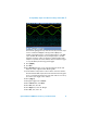
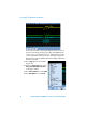
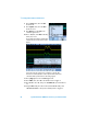
5 Press [Default Setup].
6 Press [Auto Scale].
7 Set the timebase to 500 µs/div.