
Technical data


Viewing Multiple Signals in an MCU-based Design with an MSO 5
Agilent InfiniiVision 7000B Series Oscilloscopes Evaluation Guide 33
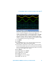
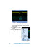
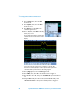
Although the oscilloscope should be triggering on a stable pattern of
“80h” on Bus1, you should be seeing two phases of the sine wave. This
is because this particular pattern occurs both when the output of the
DAC is increasing in value and decreasing in value. Let’s further qualify
the trigger condition using mixed-signal triggering (analog + digital
triggering) in order to trigger only when the DAC is increasing in value.
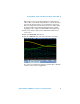
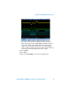
19 First, set the channel 1 vertical scale to 200 mV/div and the vertical
offset to 1.6 V.
20 Next, press Channel B1; then, select 1.
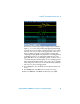
21 Now, press Pattern X ; then, select “0” as the pattern on channel 1.
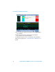
The oscilloscope should now be triggering on pattern “80h” of B1 while
channel 1 is low (or below its trigger level).