
Technical data


Viewing Multiple Signals in an MCU-based Design with an MSO 5
Agilent InfiniiVision 7000B Series Oscilloscopes Evaluation Guide 31
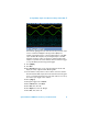
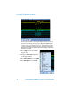
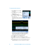
The channel 2 signal (green trace) shows the stair-step sine wave output
of microcontroller-based Digital-to-Analog Converter (DAC). The
channel 1 signal (yellow trace) is a low-pass filtered version of the DAC
output. Channels D0 – D7 (blue, red) are the digital inputs to the DAC.
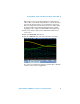
Using Auto Scale, the oscilloscope triggers on channel 2, which in this
example is a repetitive sine wave. However, what if we wanted to trigger
on a specific DAC input value using pattern trigger?
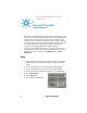
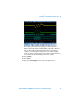
8 Press [Digital].
9 Press Bus.
10 Press Bus-Bus1 two times to turn on the bus display mode. This will
display an overlay of digital channels D0 through D7.
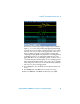
11 Set the timebase to 20 µs/div in order to read the state of this 8-bit bus.
Note that when the DAC output, which is the channel 2 waveform (green
trace), is at its highest level, Bus1 has a hex value of E6. Let’s now set up
the oscilloscope to trigger on this condition.
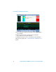
12 Press [Trigger].
13 Change the trigger mode to Pattern.
14 Press Channel; then, select Bus1.
15 Press Hex; then, select “E”.
16 Press Digit; then, select the “0” digit.
17 Press Hex ; then, select “6”.