
Technical data


92 7000 Series Oscilloscopes Service Guide
5 Replacing Assemblies
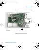
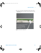
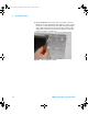
4 Carefully unlock the two alignment pins. Carefully lift
acquisition board off front deck.
Figure 23 Unlocking alignment pin
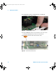
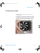
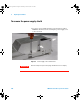
5 Using a TORX T10 driver locate and remove the two screws
securing the Dual Inverter board to the front deck.
6 Disconnect all cables, lift board off front deck.
Figure 24 Removal of inverter board
7000 service guide.book Page 92 Thursday, October 16, 2008 12:18 PM