
Technical data


90 7000 Series Oscilloscopes Service Guide
5 Replacing Assemblies
To remove Acquisition and Inverter assemblies
The following illustrates how to remove the Acquisition and
Dual inverter printed circuit boards.
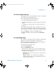
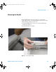
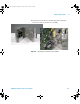
1 Using a TORK T6 driver locate and remove the 4 screws on
the front of the instrument (4 Channel version).
Figure 21 Removing the T6 screws
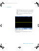
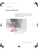
2 Disconnect Inverter, keyboard and display cables. Note
locations for re-connection. It should be noted that cables
can be removed from cable clamps at this time as well. The
cable restraining pads that affix the display cable to the front
deck are adhesive and great care should be taken when
removing them so as not to damage the cable.
7000 service guide.book Page 90 Thursday, October 16, 2008 12:18 PM