
Technical data


83
Agilent Technologies
Agilent InfiniiVision 7000 Series Oscilloscope
Service Guide
5
Replacing Assemblies
This chapter describes how to remove assemblies from the
Agilent 7000A Series Oscilloscopes. To install a replacement
assembly after you have removed an old one, follow the
instructions in reverse order.
The parts shown in the following figures are representative and
may look different from what you have in your oscilloscope.
The removable assemblies include:
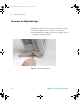
Handle (page 85)
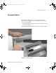
Adjustable Legs (page 86)
Cabinet (page 87)
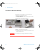
Rear Deck (page 88)
Acquisition and Inverter Assemblies(page 90)
Front Panel Assembly (page 93)
Fan Assembly (page 99)
Power Supply Shield (page 100)
Power Switch (page 102)
Power Supply (page 102)
AC Input Board (page 103)
Tools Used for Disassembly
Use these tools to remove and replace the oscilloscope
assemblies:
• T6, T10, and T20 TORX drivers
• 5/8-inch and 9/32-inch socket drivers
• Flat head screw driver
7000 service guide.book Page 83 Thursday, October 16, 2008 12:18 PM