
Technical data


26 7000 Series Oscilloscopes Service Guide
2 Testing Performance
To construct the test connector (for use with MSO models only)
Agilent 7000 Series Oscilloscopes that have digital channels
enabled require the test connector described below. Follow the
steps to build the test connector.
1 Obtain a BNC connector and an 8-by-2 section of Berg strip.
A longer strip can be cut to length using wire cutters.
2 On one side of the Berg strip, solder a jumper wire to all of
the pins (shown in Figure 1 on page 27).
3 On the other side of the Berg strip, solder another jumper
wire to all of the pins.
4 Solder the center of the BNC connector to a center pin on one
of the rows on the Berg strip.
5 Solder the ground tab of the BNC connector to a center pin
on the other row on the Berg strip.
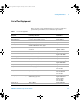
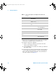
Table 3 Materials required to construct the test connectors
Description Recommended Part Qty
BNC (f) Connector Agilent 1250-1032 or
Pomona 4578
1
Berg Strip, 8-by-2 3M .100” x .100” Pin
Strip Header or similar
1 strip, cut to length (8x2)
Jumper wire
7000 service guide.book Page 26 Thursday, October 16, 2008 12:18 PM