
Technical data
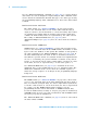
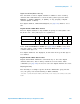
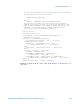
Table Of Contents
- In This Book
- Contents
- What's New
- What's New in Version 6.00
- What's New in Version 5.25
- What's New in Version 5.20
- What's New in Version 5.15
- What's New in Version 5.10
- What's New in Version 5.00
- What's New in Version 4.10
- What's New in Version 4.00
- What's New in Version 3.50
- What's New in Version 3.00
- Command Differences From 54620/54640 Series Oscilloscopes
- Setting Up
- Getting Started
- Basic Oscilloscope Program Structure
- Programming the Oscilloscope
- Referencing the IO Library
- Opening the Oscilloscope Connection via the IO Library
- Initializing the Interface and the Oscilloscope
- Using :AUToscale to Automate Oscilloscope Setup
- Using Other Oscilloscope Setup Commands
- Capturing Data with the :DIGitize Command
- Reading Query Responses from the Oscilloscope
- Reading Query Results into String Variables
- Reading Query Results into Numeric Variables
- Reading Definite-Length Block Query Response Data
- Sending Multiple Queries and Reading Results
- Checking Instrument Status
- Other Ways of Sending Commands
- Commands Quick Reference
- Commands by Subsystem
- Common (*) Commands
- *CLS (Clear Status)
- *ESE (Standard Event Status Enable)
- *ESR (Standard Event Status Register)
- *IDN (Identification Number)
- *LRN (Learn Device Setup)
- *OPC (Operation Complete)
- *OPT (Option Identification)
- *RCL (Recall)
- *RST (Reset)
- *SAV (Save)
- *SRE (Service Request Enable)
- *STB (Read Status Byte)
- *TRG (Trigger)
- *TST (Self Test)
- *WAI (Wait To Continue)
- Root (:) Commands
- :ACTivity
- :AER (Arm Event Register)
- :AUToscale
- :AUToscale:AMODE
- :AUToscale:CHANnels
- :BLANk
- :CDISplay
- :DIGitize
- :HWEenable (Hardware Event Enable Register)
- :HWERegister:CONDition (Hardware Event Condition Register)
- :HWERegister[:EVENt] (Hardware Event Event Register)
- :MERGe
- :MTEenable (Mask Test Event Enable Register)
- :MTERegister[:EVENt] (Mask Test Event Event Register)
- :OPEE (Operation Status Enable Register)
- :OPERegister:CONDition (Operation Status Condition Register)
- :OPERegister[:EVENt] (Operation Status Event Register)
- :OVLenable (Overload Event Enable Register)
- :OVLRegister (Overload Event Register)
- :RUN
- :SERial
- :SINGle
- :STATus
- :STOP
- :TER (Trigger Event Register)
- :VIEW
- :ACQuire Commands
- :BUS
Commands - :CALibrate Commands
- :CHANnel
Commands - :DIGital
Commands - :DISPlay Commands
- :EXTernal Trigger Commands
- :FUNCtion Commands
- :HARDcopy Commands
- :LISTer Commands
- :MARKer Commands
- :MEASure Commands
- :MEASure:CLEar
- :MEASure:COUNter
- :MEASure:DEFine
- :MEASure:DELay
- :MEASure:DUTYcycle
- :MEASure:FALLtime
- :MEASure:FREQuency
- :MEASure:NWIDth
- :MEASure:OVERshoot
- :MEASure:PERiod
- :MEASure:PHASe
- :MEASure:PREShoot
- :MEASure:PWIDth
- :MEASure:RESults
- :MEASure:RISetime
- :MEASure:SDEViation
- :MEASure:SHOW
- :MEASure:SOURce
- :MEASure:STATistics
- :MEASure:STATistics:INCRement
- :MEASure:STATistics:RESet
- :MEASure:TEDGe
- :MEASure:TVALue
- :MEASure:VAMPlitude
- :MEASure:VAVerage
- :MEASure:VBASe
- :MEASure:VMAX
- :MEASure:VMIN
- :MEASure:VPP
- :MEASure:VRATio
- :MEASure:VRMS
- :MEASure:VTIMe
- :MEASure:VTOP
- :MEASure:XMAX
- :MEASure:XMIN
- :MTESt Commands
- :MTESt:AMASk:CREate
- :MTESt:AMASk:SOURce
- :MTESt:AMASk:UNITs
- :MTESt:AMASk:XDELta
- :MTESt:AMASk:YDELta
- :MTESt:COUNt:FWAVeforms
- :MTESt:COUNt:RESet
- :MTESt:COUNt:TIME
- :MTESt:COUNt:WAVeforms
- :MTESt:DATA
- :MTESt:DELete
- :MTESt:ENABle
- :MTESt:LOCK
- :MTESt:OUTPut
- :MTESt:RMODe
- :MTESt:RMODe:FACTion:MEASure
- :MTESt:RMODe:FACTion:PRINt
- :MTESt:RMODe:FACTion:SAVE
- :MTESt:RMODe:FACTion:STOP
- :MTESt:RMODe:SIGMa
- :MTESt:RMODe:TIME
- :MTESt:RMODe:WAVeforms
- :MTESt:SCALe:BIND
- :MTESt:SCALe:X1
- :MTESt:SCALe:XDELta
- :MTESt:SCALe:Y1
- :MTESt:SCALe:Y2
- :MTESt:SOURce
- :MTESt:TITLe
- :POD Commands
- :RECall Commands
- :SAVE Commands
- :SBUS Commands
- :SBUS:CAN:COUNt:ERRor
- :SBUS:CAN:COUNt:OVERload
- :SBUS:CAN:COUNt:RESet
- :SBUS:CAN:COUNt:TOTal
- :SBUS:CAN:COUNt:UTILization
- :SBUS:DISPlay
- :SBUS:FLEXray:COUNt:NULL
- :SBUS:FLEXray:COUNt:RESet
- :SBUS:FLEXray:COUNt:SYNC
- :SBUS:FLEXray:COUNt:TOTal
- :SBUS:I2S:BASE
- :SBUS:IIC:ASIZe
- :SBUS:LIN:PARity
- :SBUS:M1553:BASE
- :SBUS:MODE
- :SBUS:SPI:BITorder
- :SBUS:SPI:WIDTh
- :SBUS:UART:BASE
- :SBUS:UART:COUNt:ERRor
- :SBUS:UART:COUNt:RESet
- :SBUS:UART:COUNt:RXFRames
- :SBUS:UART:COUNt:TXFRames
- :SBUS:UART:FRAMing
- :SYSTem Commands
- :TIMebase Commands
- :TRIGger Commands
- General :TRIGger Commands
- :TRIGger:HFReject
- :TRIGger:HOLDoff
- :TRIGger:MODE
- :TRIGger:NREJect
- :TRIGger:PATTern
- :TRIGger:SWEep
- :TRIGger:CAN Commands
- :TRIGger:CAN:PATTern:DATA
- :TRIGger:CAN:PATTern:DATA:LENGth
- :TRIGger:CAN:PATTern:ID
- :TRIGger:CAN:PATTern:ID:MODE
- :TRIGger:CAN:SAMPlepoint
- :TRIGger:CAN:SIGNal:BAUDrate
- :TRIGger:CAN:SOURce
- :TRIGger:CAN:TRIGger
- :TRIGger:DURation Commands
- :TRIGger:DURation:GREaterthan
- :TRIGger:DURation:LESSthan
- :TRIGger:DURation:PATTern
- :TRIGger:DURation:QUALifier
- :TRIGger:DURation:RANGe
- :TRIGger:EBURst Commands
- :TRIGger:EBURst:COUNt
- :TRIGger:EBURst:IDLE
- :TRIGger:EBURst:SLOPe
- :TRIGger[:EDGE] Commands
- :TRIGger[:EDGE]:COUPling
- :TRIGger[:EDGE]:LEVel
- :TRIGger[:EDGE]:REJect
- :TRIGger[:EDGE]:SLOPe
- :TRIGger[:EDGE]:SOURce
- :TRIGger:FLEXray Commands
- :TRIGger:FLEXray:AUTosetup
- :TRIGger:FLEXray:BAUDrate
- :TRIGger:FLEXray:CHANnel
- :TRIGger:FLEXray:ERRor:TYPE
- :TRIGger:FLEXray:EVENt:TYPE
- :TRIGger:FLEXray:FRAMe:CCBase
- :TRIGger:FLEXray:FRAMe:CCRepetition
- :TRIGger:FLEXray:FRAMe:ID
- :TRIGger:FLEXray:FRAMe:TYPE
- :TRIGger:FLEXray:SOURce
- :TRIGger:FLEXray:TRIGger
- :TRIGger:GLITch Commands
- :TRIGger:GLITch:GREaterthan
- :TRIGger:GLITch:LESSthan
- :TRIGger:GLITch:LEVel
- :TRIGger:GLITch:POLarity
- :TRIGger:GLITch:QUALifier
- :TRIGger:GLITch:RANGe
- :TRIGger:GLITch:SOURce
- :TRIGger:I2S Commands
- :TRIGger:I2S:ALIGnment
- :TRIGger:I2S:AUDio
- :TRIGger:I2S:CLOCk:SLOPe
- :TRIGger:I2S:PATTern:DATA
- :TRIGger:I2S:PATTern:FORMat
- :TRIGger:I2S:RANGe
- :TRIGger:I2S:RWIDth
- :TRIGger:I2S:SOURce:CLOCk
- :TRIGger:I2S:SOURce:DATA
- :TRIGger:I2S:SOURce:WSELect
- :TRIGger:I2S:TRIGger
- :TRIGger:I2S:TWIDth
- :TRIGger:I2S:WSLow
- :TRIGger:IIC Commands
- :TRIGger:IIC:PATTern:ADDRess
- :TRIGger:IIC:PATTern:DATA
- :TRIGger:IIC:PATTern:DATa2
- :TRIGger:IIC[:SOURce]:CLOCk
- :TRIGger:IIC[:SOURce]:DATA
- :TRIGger:IIC:TRIGger:QUALifier
- :TRIGger:IIC:TRIGger[:TYPE]
- :TRIGger:LIN Commands
- :TRIGger:LIN:ID
- :TRIGger:LIN:PATTern:DATA
- :TRIGger:LIN:PATTern:DATA:LENGth
- :TRIGger:LIN:PATTern:FORMat
- :TRIGger:LIN:SAMPlepoint
- :TRIGger:LIN:SIGNal:BAUDrate
- :TRIGger:LIN:SOURce
- :TRIGger:LIN:STANdard
- :TRIGger:LIN:SYNCbreak
- :TRIGger:LIN:TRIGger
- :TRIGger:M1553 Commands
- :TRIGger:M1553:AUTosetup
- :TRIGger:M1553:PATTern:DATA
- :TRIGger:M1553:RTA
- :TRIGger:M1553:SOURce:LOWer
- :TRIGger:M1553:SOURce:UPPer
- :TRIGger:M1553:TYPE
- :TRIGger:SEQuence Commands
- :TRIGger:SEQuence:COUNt
- :TRIGger:SEQuence:EDGE
- :TRIGger:SEQuence:FIND
- :TRIGger:SEQuence:PATTern
- :TRIGger:SEQuence:RESet
- :TRIGger:SEQuence:TIMer
- :TRIGger:SEQuence:TRIGger
- :TRIGger:SPI Commands
- :TRIGger:SPI:CLOCk:SLOPe
- :TRIGger:SPI:CLOCk:TIMeout
- :TRIGger:SPI:FRAMing
- :TRIGger:SPI:PATTern:DATA
- :TRIGger:SPI:PATTern:WIDTh
- :TRIGger:SPI:SOURce:CLOCk
- :TRIGger:SPI:SOURce:DATA
- :TRIGger:SPI:SOURce:FRAMe
- :TRIGger:TV Commands
- :TRIGger:TV:LINE
- :TRIGger:TV:MODE
- :TRIGger:TV:POLarity
- :TRIGger:TV:SOURce
- :TRIGger:TV:STANdard
- :TRIGger:UART Commands
- :TRIGger:UART:BASE
- :TRIGger:UART:BAUDrate
- :TRIGger:UART:BITorder
- :TRIGger:UART:BURSt
- :TRIGger:UART:DATA
- :TRIGger:UART:IDLE
- :TRIGger:UART:PARity
- :TRIGger:UART:POLarity
- :TRIGger:UART:QUALifier
- :TRIGger:UART:SOURce:RX
- :TRIGger:UART:SOURce:TX
- :TRIGger:UART:TYPE
- :TRIGger:UART:WIDTh
- :TRIGger:USB Commands
- :TRIGger:USB:SOURce:DMINus
- :TRIGger:USB:SOURce:DPLus
- :TRIGger:USB:SPEed
- :TRIGger:USB:TRIGger
- :WAVeform Commands
- :WAVeform:BYTeorder
- :WAVeform:COUNt
- :WAVeform:DATA
- :WAVeform:FORMat
- :WAVeform:POINts
- :WAVeform:POINts:MODE
- :WAVeform:PREamble
- :WAVeform:SEGMented:COUNt
- :WAVeform:SEGMented:TTAG
- :WAVeform:SOURce
- :WAVeform:SOURce:SUBSource
- :WAVeform:TYPE
- :WAVeform:UNSigned
- :WAVeform:VIEW
- :WAVeform:XINCrement
- :WAVeform:XORigin
- :WAVeform:XREFerence
- :WAVeform:YINCrement
- :WAVeform:YORigin
- :WAVeform:YREFerence
- Common (*) Commands
- Commands A-Z
- Obsolete and Discontinued Commands
- :CHANnel:ACTivity
- :CHANnel:LABel
- :CHANnel:THReshold
- :CHANnel2:SKEW
- :CHANnel
:INPut - :CHANnel
:PMODe - :DISPlay:CONNect
- :DISPlay:ORDer
- :ERASe
- :EXTernal:INPut
- :EXTernal:PMODe
- :FUNCtion:SOURce
- :FUNCtion:VIEW
- :HARDcopy:DESTination
- :HARDcopy:DEVice
- :HARDcopy:FILename
- :HARDcopy:FORMat
- :HARDcopy:GRAYscale
- :HARDcopy:IGColors
- :HARDcopy:PDRiver
- :MEASure:LOWer
- :MEASure:SCRatch
- :MEASure:TDELta
- :MEASure:THResholds
- :MEASure:TMAX
- :MEASure:TMIN
- :MEASure:TSTArt
- :MEASure:TSTOp
- :MEASure:TVOLt
- :MEASure:UPPer
- :MEASure:VDELta
- :MEASure:VSTArt
- :MEASure:VSTOp
- :MTESt:AMASk:{SAVE | STORe}
- :MTESt:AVERage
- :MTESt:AVERage:COUNt
- :MTESt:LOAD
- :MTESt:RUMode
- :MTESt:RUMode:SOFailure
- :MTESt:{STARt | STOP}
- :MTESt:TRIGger:SOURce
- :PRINt?
- :TIMebase:DELay
- :TRIGger:CAN:ACKNowledge
- :TRIGger:CAN:SIGNal:DEFinition
- :TRIGger:LIN:SIGNal:DEFinition
- :TRIGger:THReshold
- :TRIGger:TV:TVMode
- Error Messages
- Status Reporting
- Status Reporting Data Structures
- Status Byte Register (STB)
- Service Request Enable Register (SRE)
- Trigger Event Register (TER)
- Output Queue
- Message Queue
- (Standard) Event Status Register (ESR)
- (Standard) Event Status Enable Register (ESE)
- Error Queue
- Operation Status Event Register (:OPERegister[:EVENt])
- Operation Status Condition Register (:OPERegister:CONDition)
- Arm Event Register (AER)
- Overload Event Register (:OVLRegister)
- Hardware Event Event Register (:HWERegister[:EVENt])
- Hardware Event Condition Register (:HWERegister:CONDition)
- Mask Test Event Event Register (:MTERegister[:EVENt])
- Clearing Registers and Queues
- Status Reporting Decision Chart
- Synchronizing Acquisitions
- More About Oscilloscope Commands
- Programming Examples
- Index

Commands by Subsystem 5
Agilent InfiniiVision 6000 Series Oscilloscopes Programmer's Guide 635
Digital Channel Data (MSO models only)
The waveform record for digital channels is similar to that of analog
channels. The main difference is that the data points represent either
DIGital0,..,7 (POD1), DIGital8,..,15 (POD2), or any grouping of digital
channels (BUS1 or BUS2).
For digital channels, :WAVeform:UNSigned (see page 656) must be set to
ON.
Digital Channel POD Data Format
Data for digital channels is only available in groups of 8 bits (Pod1 = D0 -
D7, Pod2 = D8 - D15). The bytes are organized as:
If the :WAVeform:FORMat is WORD (see page 640) is WORD, every other
data byte will be 0. The setting of :WAVeform:BYTeorder (see page 636)
controls which byte is 0.
If a digital channel is not displayed, its bit value in the pod data byte is
not defined.
Digital Channel BUS Data Format
Digital channel BUS definitions can include any or all of the digital
channels. Therefore, data is always returned as 16- bit values. :BUS
commands (see page 210) are used to select the digital channels for a bus.
Reporting the Setup
The following is a sample response from the :WAVeform? query. In this
case, the query was issued following a *RST command.
:WAV:UNS 1;VIEW MAIN;BYT MSBF;FORM BYTE;POIN +1000;SOUR CHAN1;SOUR:SUBS
NONE
:WAVeform:SOURce Bit 7Bit 6Bit 5 Bit 4 Bit 3 Bit 2 Bit 1 Bit 0
POD1 D7 D6 D5 D4 D3 D2 D1 D0
POD2 D15 D14 D13 D12 D11 D10 D9 D8