
Technical data
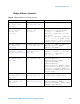

Table Of Contents
- In This Book
- Contents
- What's New
- What's New in Version 6.00
- What's New in Version 5.25
- What's New in Version 5.20
- What's New in Version 5.15
- What's New in Version 5.10
- What's New in Version 5.00
- What's New in Version 4.10
- What's New in Version 4.00
- What's New in Version 3.50
- What's New in Version 3.00
- Command Differences From 54620/54640 Series Oscilloscopes
- Setting Up
- Getting Started
- Basic Oscilloscope Program Structure
- Programming the Oscilloscope
- Referencing the IO Library
- Opening the Oscilloscope Connection via the IO Library
- Initializing the Interface and the Oscilloscope
- Using :AUToscale to Automate Oscilloscope Setup
- Using Other Oscilloscope Setup Commands
- Capturing Data with the :DIGitize Command
- Reading Query Responses from the Oscilloscope
- Reading Query Results into String Variables
- Reading Query Results into Numeric Variables
- Reading Definite-Length Block Query Response Data
- Sending Multiple Queries and Reading Results
- Checking Instrument Status
- Other Ways of Sending Commands
- Commands Quick Reference
- Commands by Subsystem
- Common (*) Commands
- *CLS (Clear Status)
- *ESE (Standard Event Status Enable)
- *ESR (Standard Event Status Register)
- *IDN (Identification Number)
- *LRN (Learn Device Setup)
- *OPC (Operation Complete)
- *OPT (Option Identification)
- *RCL (Recall)
- *RST (Reset)
- *SAV (Save)
- *SRE (Service Request Enable)
- *STB (Read Status Byte)
- *TRG (Trigger)
- *TST (Self Test)
- *WAI (Wait To Continue)
- Root (:) Commands
- :ACTivity
- :AER (Arm Event Register)
- :AUToscale
- :AUToscale:AMODE
- :AUToscale:CHANnels
- :BLANk
- :CDISplay
- :DIGitize
- :HWEenable (Hardware Event Enable Register)
- :HWERegister:CONDition (Hardware Event Condition Register)
- :HWERegister[:EVENt] (Hardware Event Event Register)
- :MERGe
- :MTEenable (Mask Test Event Enable Register)
- :MTERegister[:EVENt] (Mask Test Event Event Register)
- :OPEE (Operation Status Enable Register)
- :OPERegister:CONDition (Operation Status Condition Register)
- :OPERegister[:EVENt] (Operation Status Event Register)
- :OVLenable (Overload Event Enable Register)
- :OVLRegister (Overload Event Register)
- :RUN
- :SERial
- :SINGle
- :STATus
- :STOP
- :TER (Trigger Event Register)
- :VIEW
- :ACQuire Commands
- :BUS
Commands - :CALibrate Commands
- :CHANnel
Commands - :DIGital
Commands - :DISPlay Commands
- :EXTernal Trigger Commands
- :FUNCtion Commands
- :HARDcopy Commands
- :LISTer Commands
- :MARKer Commands
- :MEASure Commands
- :MEASure:CLEar
- :MEASure:COUNter
- :MEASure:DEFine
- :MEASure:DELay
- :MEASure:DUTYcycle
- :MEASure:FALLtime
- :MEASure:FREQuency
- :MEASure:NWIDth
- :MEASure:OVERshoot
- :MEASure:PERiod
- :MEASure:PHASe
- :MEASure:PREShoot
- :MEASure:PWIDth
- :MEASure:RESults
- :MEASure:RISetime
- :MEASure:SDEViation
- :MEASure:SHOW
- :MEASure:SOURce
- :MEASure:STATistics
- :MEASure:STATistics:INCRement
- :MEASure:STATistics:RESet
- :MEASure:TEDGe
- :MEASure:TVALue
- :MEASure:VAMPlitude
- :MEASure:VAVerage
- :MEASure:VBASe
- :MEASure:VMAX
- :MEASure:VMIN
- :MEASure:VPP
- :MEASure:VRATio
- :MEASure:VRMS
- :MEASure:VTIMe
- :MEASure:VTOP
- :MEASure:XMAX
- :MEASure:XMIN
- :MTESt Commands
- :MTESt:AMASk:CREate
- :MTESt:AMASk:SOURce
- :MTESt:AMASk:UNITs
- :MTESt:AMASk:XDELta
- :MTESt:AMASk:YDELta
- :MTESt:COUNt:FWAVeforms
- :MTESt:COUNt:RESet
- :MTESt:COUNt:TIME
- :MTESt:COUNt:WAVeforms
- :MTESt:DATA
- :MTESt:DELete
- :MTESt:ENABle
- :MTESt:LOCK
- :MTESt:OUTPut
- :MTESt:RMODe
- :MTESt:RMODe:FACTion:MEASure
- :MTESt:RMODe:FACTion:PRINt
- :MTESt:RMODe:FACTion:SAVE
- :MTESt:RMODe:FACTion:STOP
- :MTESt:RMODe:SIGMa
- :MTESt:RMODe:TIME
- :MTESt:RMODe:WAVeforms
- :MTESt:SCALe:BIND
- :MTESt:SCALe:X1
- :MTESt:SCALe:XDELta
- :MTESt:SCALe:Y1
- :MTESt:SCALe:Y2
- :MTESt:SOURce
- :MTESt:TITLe
- :POD Commands
- :RECall Commands
- :SAVE Commands
- :SBUS Commands
- :SBUS:CAN:COUNt:ERRor
- :SBUS:CAN:COUNt:OVERload
- :SBUS:CAN:COUNt:RESet
- :SBUS:CAN:COUNt:TOTal
- :SBUS:CAN:COUNt:UTILization
- :SBUS:DISPlay
- :SBUS:FLEXray:COUNt:NULL
- :SBUS:FLEXray:COUNt:RESet
- :SBUS:FLEXray:COUNt:SYNC
- :SBUS:FLEXray:COUNt:TOTal
- :SBUS:I2S:BASE
- :SBUS:IIC:ASIZe
- :SBUS:LIN:PARity
- :SBUS:M1553:BASE
- :SBUS:MODE
- :SBUS:SPI:BITorder
- :SBUS:SPI:WIDTh
- :SBUS:UART:BASE
- :SBUS:UART:COUNt:ERRor
- :SBUS:UART:COUNt:RESet
- :SBUS:UART:COUNt:RXFRames
- :SBUS:UART:COUNt:TXFRames
- :SBUS:UART:FRAMing
- :SYSTem Commands
- :TIMebase Commands
- :TRIGger Commands
- General :TRIGger Commands
- :TRIGger:HFReject
- :TRIGger:HOLDoff
- :TRIGger:MODE
- :TRIGger:NREJect
- :TRIGger:PATTern
- :TRIGger:SWEep
- :TRIGger:CAN Commands
- :TRIGger:CAN:PATTern:DATA
- :TRIGger:CAN:PATTern:DATA:LENGth
- :TRIGger:CAN:PATTern:ID
- :TRIGger:CAN:PATTern:ID:MODE
- :TRIGger:CAN:SAMPlepoint
- :TRIGger:CAN:SIGNal:BAUDrate
- :TRIGger:CAN:SOURce
- :TRIGger:CAN:TRIGger
- :TRIGger:DURation Commands
- :TRIGger:DURation:GREaterthan
- :TRIGger:DURation:LESSthan
- :TRIGger:DURation:PATTern
- :TRIGger:DURation:QUALifier
- :TRIGger:DURation:RANGe
- :TRIGger:EBURst Commands
- :TRIGger:EBURst:COUNt
- :TRIGger:EBURst:IDLE
- :TRIGger:EBURst:SLOPe
- :TRIGger[:EDGE] Commands
- :TRIGger[:EDGE]:COUPling
- :TRIGger[:EDGE]:LEVel
- :TRIGger[:EDGE]:REJect
- :TRIGger[:EDGE]:SLOPe
- :TRIGger[:EDGE]:SOURce
- :TRIGger:FLEXray Commands
- :TRIGger:FLEXray:AUTosetup
- :TRIGger:FLEXray:BAUDrate
- :TRIGger:FLEXray:CHANnel
- :TRIGger:FLEXray:ERRor:TYPE
- :TRIGger:FLEXray:EVENt:TYPE
- :TRIGger:FLEXray:FRAMe:CCBase
- :TRIGger:FLEXray:FRAMe:CCRepetition
- :TRIGger:FLEXray:FRAMe:ID
- :TRIGger:FLEXray:FRAMe:TYPE
- :TRIGger:FLEXray:SOURce
- :TRIGger:FLEXray:TRIGger
- :TRIGger:GLITch Commands
- :TRIGger:GLITch:GREaterthan
- :TRIGger:GLITch:LESSthan
- :TRIGger:GLITch:LEVel
- :TRIGger:GLITch:POLarity
- :TRIGger:GLITch:QUALifier
- :TRIGger:GLITch:RANGe
- :TRIGger:GLITch:SOURce
- :TRIGger:I2S Commands
- :TRIGger:I2S:ALIGnment
- :TRIGger:I2S:AUDio
- :TRIGger:I2S:CLOCk:SLOPe
- :TRIGger:I2S:PATTern:DATA
- :TRIGger:I2S:PATTern:FORMat
- :TRIGger:I2S:RANGe
- :TRIGger:I2S:RWIDth
- :TRIGger:I2S:SOURce:CLOCk
- :TRIGger:I2S:SOURce:DATA
- :TRIGger:I2S:SOURce:WSELect
- :TRIGger:I2S:TRIGger
- :TRIGger:I2S:TWIDth
- :TRIGger:I2S:WSLow
- :TRIGger:IIC Commands
- :TRIGger:IIC:PATTern:ADDRess
- :TRIGger:IIC:PATTern:DATA
- :TRIGger:IIC:PATTern:DATa2
- :TRIGger:IIC[:SOURce]:CLOCk
- :TRIGger:IIC[:SOURce]:DATA
- :TRIGger:IIC:TRIGger:QUALifier
- :TRIGger:IIC:TRIGger[:TYPE]
- :TRIGger:LIN Commands
- :TRIGger:LIN:ID
- :TRIGger:LIN:PATTern:DATA
- :TRIGger:LIN:PATTern:DATA:LENGth
- :TRIGger:LIN:PATTern:FORMat
- :TRIGger:LIN:SAMPlepoint
- :TRIGger:LIN:SIGNal:BAUDrate
- :TRIGger:LIN:SOURce
- :TRIGger:LIN:STANdard
- :TRIGger:LIN:SYNCbreak
- :TRIGger:LIN:TRIGger
- :TRIGger:M1553 Commands
- :TRIGger:M1553:AUTosetup
- :TRIGger:M1553:PATTern:DATA
- :TRIGger:M1553:RTA
- :TRIGger:M1553:SOURce:LOWer
- :TRIGger:M1553:SOURce:UPPer
- :TRIGger:M1553:TYPE
- :TRIGger:SEQuence Commands
- :TRIGger:SEQuence:COUNt
- :TRIGger:SEQuence:EDGE
- :TRIGger:SEQuence:FIND
- :TRIGger:SEQuence:PATTern
- :TRIGger:SEQuence:RESet
- :TRIGger:SEQuence:TIMer
- :TRIGger:SEQuence:TRIGger
- :TRIGger:SPI Commands
- :TRIGger:SPI:CLOCk:SLOPe
- :TRIGger:SPI:CLOCk:TIMeout
- :TRIGger:SPI:FRAMing
- :TRIGger:SPI:PATTern:DATA
- :TRIGger:SPI:PATTern:WIDTh
- :TRIGger:SPI:SOURce:CLOCk
- :TRIGger:SPI:SOURce:DATA
- :TRIGger:SPI:SOURce:FRAMe
- :TRIGger:TV Commands
- :TRIGger:TV:LINE
- :TRIGger:TV:MODE
- :TRIGger:TV:POLarity
- :TRIGger:TV:SOURce
- :TRIGger:TV:STANdard
- :TRIGger:UART Commands
- :TRIGger:UART:BASE
- :TRIGger:UART:BAUDrate
- :TRIGger:UART:BITorder
- :TRIGger:UART:BURSt
- :TRIGger:UART:DATA
- :TRIGger:UART:IDLE
- :TRIGger:UART:PARity
- :TRIGger:UART:POLarity
- :TRIGger:UART:QUALifier
- :TRIGger:UART:SOURce:RX
- :TRIGger:UART:SOURce:TX
- :TRIGger:UART:TYPE
- :TRIGger:UART:WIDTh
- :TRIGger:USB Commands
- :TRIGger:USB:SOURce:DMINus
- :TRIGger:USB:SOURce:DPLus
- :TRIGger:USB:SPEed
- :TRIGger:USB:TRIGger
- :WAVeform Commands
- :WAVeform:BYTeorder
- :WAVeform:COUNt
- :WAVeform:DATA
- :WAVeform:FORMat
- :WAVeform:POINts
- :WAVeform:POINts:MODE
- :WAVeform:PREamble
- :WAVeform:SEGMented:COUNt
- :WAVeform:SEGMented:TTAG
- :WAVeform:SOURce
- :WAVeform:SOURce:SUBSource
- :WAVeform:TYPE
- :WAVeform:UNSigned
- :WAVeform:VIEW
- :WAVeform:XINCrement
- :WAVeform:XORigin
- :WAVeform:XREFerence
- :WAVeform:YINCrement
- :WAVeform:YORigin
- :WAVeform:YREFerence
- Common (*) Commands
- Commands A-Z
- Obsolete and Discontinued Commands
- :CHANnel:ACTivity
- :CHANnel:LABel
- :CHANnel:THReshold
- :CHANnel2:SKEW
- :CHANnel
:INPut - :CHANnel
:PMODe - :DISPlay:CONNect
- :DISPlay:ORDer
- :ERASe
- :EXTernal:INPut
- :EXTernal:PMODe
- :FUNCtion:SOURce
- :FUNCtion:VIEW
- :HARDcopy:DESTination
- :HARDcopy:DEVice
- :HARDcopy:FILename
- :HARDcopy:FORMat
- :HARDcopy:GRAYscale
- :HARDcopy:IGColors
- :HARDcopy:PDRiver
- :MEASure:LOWer
- :MEASure:SCRatch
- :MEASure:TDELta
- :MEASure:THResholds
- :MEASure:TMAX
- :MEASure:TMIN
- :MEASure:TSTArt
- :MEASure:TSTOp
- :MEASure:TVOLt
- :MEASure:UPPer
- :MEASure:VDELta
- :MEASure:VSTArt
- :MEASure:VSTOp
- :MTESt:AMASk:{SAVE | STORe}
- :MTESt:AVERage
- :MTESt:AVERage:COUNt
- :MTESt:LOAD
- :MTESt:RUMode
- :MTESt:RUMode:SOFailure
- :MTESt:{STARt | STOP}
- :MTESt:TRIGger:SOURce
- :PRINt?
- :TIMebase:DELay
- :TRIGger:CAN:ACKNowledge
- :TRIGger:CAN:SIGNal:DEFinition
- :TRIGger:LIN:SIGNal:DEFinition
- :TRIGger:THReshold
- :TRIGger:TV:TVMode
- Error Messages
- Status Reporting
- Status Reporting Data Structures
- Status Byte Register (STB)
- Service Request Enable Register (SRE)
- Trigger Event Register (TER)
- Output Queue
- Message Queue
- (Standard) Event Status Register (ESR)
- (Standard) Event Status Enable Register (ESE)
- Error Queue
- Operation Status Event Register (:OPERegister[:EVENt])
- Operation Status Condition Register (:OPERegister:CONDition)
- Arm Event Register (AER)
- Overload Event Register (:OVLRegister)
- Hardware Event Event Register (:HWERegister[:EVENt])
- Hardware Event Condition Register (:HWERegister:CONDition)
- Mask Test Event Event Register (:MTERegister[:EVENt])
- Clearing Registers and Queues
- Status Reporting Decision Chart
- Synchronizing Acquisitions
- More About Oscilloscope Commands
- Programming Examples
- Index

Commands by Subsystem 5
Agilent InfiniiVision 6000 Series Oscilloscopes Programmer's Guide 589
:TRIGger:SEQuence:PATTern
(see page 798)
Command Syntax
:TRIGger:SEQuence:PATTern{1 | 2} <value>,<mask>
<value> ::= integer or <string>
<mask> ::= integer or <string>
<string> ::= "0xnnnnnn" where n ::= {0,..,9 | A,..,F}
The :TRIGger:SEQuence:PATTern<n> command defines the specified
sequence pattern resource according to the value and the mask. For both
<value> and <mask>, each bit corresponds to a possible trigger channel.
The bit assignments vary by instrument:
Set a <value> bit to "0" to set the pattern for the corresponding channel to
low. Set a <value> bit to "1" to set the pattern to high.
Set a <mask> bit to "0" to ignore the data for the corresponding channel.
Only channels with a "1" set on the appropriate mask bit are used.
Query Syntax
:TRIGger:SEQuence:PATTern{1 | 2}?
The :TRIGger:SEQuence:PATTern<n>? query returns the current settings of
the specified pattern resource.
Return Format
<value>, <mask><NL>
See Also • "Introduction to :TRIGger Commands" on page 479
• ":TRIGger:SEQuence:FIND" on page 588
• ":TRIGger:SEQuence:TRIGger" on page 592
• ":TRIGger:SEQuence:RESet" on page 590
Oscilloscope Models Value and Mask Bit Assignments
4 analog + 16 digital channels (mixed-signal) Bits 0 through 15 - digital channels 0 through
15. Bits 16 through 19 - analog channels 1
through 4.
2 analog + 16 digital channels (mixed-signal) Bits 0 through 15 - digital channels 0 through
15. Bits 16 and 17 - analog channels 1 and 2.
4 analog channels only Bits 0 through 3 - analog channels 1 through 4.
Bit 4 - external trigger.
2 analog channels only Bits 0 and 1 - analog channels 1 and 2. Bit 4 -
external trigger.