
Technical data
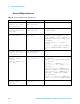
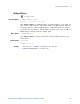

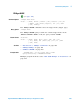
Table Of Contents
- In This Book
- Contents
- What's New
- What's New in Version 6.00
- What's New in Version 5.25
- What's New in Version 5.20
- What's New in Version 5.15
- What's New in Version 5.10
- What's New in Version 5.00
- What's New in Version 4.10
- What's New in Version 4.00
- What's New in Version 3.50
- What's New in Version 3.00
- Command Differences From 54620/54640 Series Oscilloscopes
- Setting Up
- Getting Started
- Basic Oscilloscope Program Structure
- Programming the Oscilloscope
- Referencing the IO Library
- Opening the Oscilloscope Connection via the IO Library
- Initializing the Interface and the Oscilloscope
- Using :AUToscale to Automate Oscilloscope Setup
- Using Other Oscilloscope Setup Commands
- Capturing Data with the :DIGitize Command
- Reading Query Responses from the Oscilloscope
- Reading Query Results into String Variables
- Reading Query Results into Numeric Variables
- Reading Definite-Length Block Query Response Data
- Sending Multiple Queries and Reading Results
- Checking Instrument Status
- Other Ways of Sending Commands
- Commands Quick Reference
- Commands by Subsystem
- Common (*) Commands
- *CLS (Clear Status)
- *ESE (Standard Event Status Enable)
- *ESR (Standard Event Status Register)
- *IDN (Identification Number)
- *LRN (Learn Device Setup)
- *OPC (Operation Complete)
- *OPT (Option Identification)
- *RCL (Recall)
- *RST (Reset)
- *SAV (Save)
- *SRE (Service Request Enable)
- *STB (Read Status Byte)
- *TRG (Trigger)
- *TST (Self Test)
- *WAI (Wait To Continue)
- Root (:) Commands
- :ACTivity
- :AER (Arm Event Register)
- :AUToscale
- :AUToscale:AMODE
- :AUToscale:CHANnels
- :BLANk
- :CDISplay
- :DIGitize
- :HWEenable (Hardware Event Enable Register)
- :HWERegister:CONDition (Hardware Event Condition Register)
- :HWERegister[:EVENt] (Hardware Event Event Register)
- :MERGe
- :MTEenable (Mask Test Event Enable Register)
- :MTERegister[:EVENt] (Mask Test Event Event Register)
- :OPEE (Operation Status Enable Register)
- :OPERegister:CONDition (Operation Status Condition Register)
- :OPERegister[:EVENt] (Operation Status Event Register)
- :OVLenable (Overload Event Enable Register)
- :OVLRegister (Overload Event Register)
- :RUN
- :SERial
- :SINGle
- :STATus
- :STOP
- :TER (Trigger Event Register)
- :VIEW
- :ACQuire Commands
- :BUS
Commands - :CALibrate Commands
- :CHANnel
Commands - :DIGital
Commands - :DISPlay Commands
- :EXTernal Trigger Commands
- :FUNCtion Commands
- :HARDcopy Commands
- :LISTer Commands
- :MARKer Commands
- :MEASure Commands
- :MEASure:CLEar
- :MEASure:COUNter
- :MEASure:DEFine
- :MEASure:DELay
- :MEASure:DUTYcycle
- :MEASure:FALLtime
- :MEASure:FREQuency
- :MEASure:NWIDth
- :MEASure:OVERshoot
- :MEASure:PERiod
- :MEASure:PHASe
- :MEASure:PREShoot
- :MEASure:PWIDth
- :MEASure:RESults
- :MEASure:RISetime
- :MEASure:SDEViation
- :MEASure:SHOW
- :MEASure:SOURce
- :MEASure:STATistics
- :MEASure:STATistics:INCRement
- :MEASure:STATistics:RESet
- :MEASure:TEDGe
- :MEASure:TVALue
- :MEASure:VAMPlitude
- :MEASure:VAVerage
- :MEASure:VBASe
- :MEASure:VMAX
- :MEASure:VMIN
- :MEASure:VPP
- :MEASure:VRATio
- :MEASure:VRMS
- :MEASure:VTIMe
- :MEASure:VTOP
- :MEASure:XMAX
- :MEASure:XMIN
- :MTESt Commands
- :MTESt:AMASk:CREate
- :MTESt:AMASk:SOURce
- :MTESt:AMASk:UNITs
- :MTESt:AMASk:XDELta
- :MTESt:AMASk:YDELta
- :MTESt:COUNt:FWAVeforms
- :MTESt:COUNt:RESet
- :MTESt:COUNt:TIME
- :MTESt:COUNt:WAVeforms
- :MTESt:DATA
- :MTESt:DELete
- :MTESt:ENABle
- :MTESt:LOCK
- :MTESt:OUTPut
- :MTESt:RMODe
- :MTESt:RMODe:FACTion:MEASure
- :MTESt:RMODe:FACTion:PRINt
- :MTESt:RMODe:FACTion:SAVE
- :MTESt:RMODe:FACTion:STOP
- :MTESt:RMODe:SIGMa
- :MTESt:RMODe:TIME
- :MTESt:RMODe:WAVeforms
- :MTESt:SCALe:BIND
- :MTESt:SCALe:X1
- :MTESt:SCALe:XDELta
- :MTESt:SCALe:Y1
- :MTESt:SCALe:Y2
- :MTESt:SOURce
- :MTESt:TITLe
- :POD Commands
- :RECall Commands
- :SAVE Commands
- :SBUS Commands
- :SBUS:CAN:COUNt:ERRor
- :SBUS:CAN:COUNt:OVERload
- :SBUS:CAN:COUNt:RESet
- :SBUS:CAN:COUNt:TOTal
- :SBUS:CAN:COUNt:UTILization
- :SBUS:DISPlay
- :SBUS:FLEXray:COUNt:NULL
- :SBUS:FLEXray:COUNt:RESet
- :SBUS:FLEXray:COUNt:SYNC
- :SBUS:FLEXray:COUNt:TOTal
- :SBUS:I2S:BASE
- :SBUS:IIC:ASIZe
- :SBUS:LIN:PARity
- :SBUS:M1553:BASE
- :SBUS:MODE
- :SBUS:SPI:BITorder
- :SBUS:SPI:WIDTh
- :SBUS:UART:BASE
- :SBUS:UART:COUNt:ERRor
- :SBUS:UART:COUNt:RESet
- :SBUS:UART:COUNt:RXFRames
- :SBUS:UART:COUNt:TXFRames
- :SBUS:UART:FRAMing
- :SYSTem Commands
- :TIMebase Commands
- :TRIGger Commands
- General :TRIGger Commands
- :TRIGger:HFReject
- :TRIGger:HOLDoff
- :TRIGger:MODE
- :TRIGger:NREJect
- :TRIGger:PATTern
- :TRIGger:SWEep
- :TRIGger:CAN Commands
- :TRIGger:CAN:PATTern:DATA
- :TRIGger:CAN:PATTern:DATA:LENGth
- :TRIGger:CAN:PATTern:ID
- :TRIGger:CAN:PATTern:ID:MODE
- :TRIGger:CAN:SAMPlepoint
- :TRIGger:CAN:SIGNal:BAUDrate
- :TRIGger:CAN:SOURce
- :TRIGger:CAN:TRIGger
- :TRIGger:DURation Commands
- :TRIGger:DURation:GREaterthan
- :TRIGger:DURation:LESSthan
- :TRIGger:DURation:PATTern
- :TRIGger:DURation:QUALifier
- :TRIGger:DURation:RANGe
- :TRIGger:EBURst Commands
- :TRIGger:EBURst:COUNt
- :TRIGger:EBURst:IDLE
- :TRIGger:EBURst:SLOPe
- :TRIGger[:EDGE] Commands
- :TRIGger[:EDGE]:COUPling
- :TRIGger[:EDGE]:LEVel
- :TRIGger[:EDGE]:REJect
- :TRIGger[:EDGE]:SLOPe
- :TRIGger[:EDGE]:SOURce
- :TRIGger:FLEXray Commands
- :TRIGger:FLEXray:AUTosetup
- :TRIGger:FLEXray:BAUDrate
- :TRIGger:FLEXray:CHANnel
- :TRIGger:FLEXray:ERRor:TYPE
- :TRIGger:FLEXray:EVENt:TYPE
- :TRIGger:FLEXray:FRAMe:CCBase
- :TRIGger:FLEXray:FRAMe:CCRepetition
- :TRIGger:FLEXray:FRAMe:ID
- :TRIGger:FLEXray:FRAMe:TYPE
- :TRIGger:FLEXray:SOURce
- :TRIGger:FLEXray:TRIGger
- :TRIGger:GLITch Commands
- :TRIGger:GLITch:GREaterthan
- :TRIGger:GLITch:LESSthan
- :TRIGger:GLITch:LEVel
- :TRIGger:GLITch:POLarity
- :TRIGger:GLITch:QUALifier
- :TRIGger:GLITch:RANGe
- :TRIGger:GLITch:SOURce
- :TRIGger:I2S Commands
- :TRIGger:I2S:ALIGnment
- :TRIGger:I2S:AUDio
- :TRIGger:I2S:CLOCk:SLOPe
- :TRIGger:I2S:PATTern:DATA
- :TRIGger:I2S:PATTern:FORMat
- :TRIGger:I2S:RANGe
- :TRIGger:I2S:RWIDth
- :TRIGger:I2S:SOURce:CLOCk
- :TRIGger:I2S:SOURce:DATA
- :TRIGger:I2S:SOURce:WSELect
- :TRIGger:I2S:TRIGger
- :TRIGger:I2S:TWIDth
- :TRIGger:I2S:WSLow
- :TRIGger:IIC Commands
- :TRIGger:IIC:PATTern:ADDRess
- :TRIGger:IIC:PATTern:DATA
- :TRIGger:IIC:PATTern:DATa2
- :TRIGger:IIC[:SOURce]:CLOCk
- :TRIGger:IIC[:SOURce]:DATA
- :TRIGger:IIC:TRIGger:QUALifier
- :TRIGger:IIC:TRIGger[:TYPE]
- :TRIGger:LIN Commands
- :TRIGger:LIN:ID
- :TRIGger:LIN:PATTern:DATA
- :TRIGger:LIN:PATTern:DATA:LENGth
- :TRIGger:LIN:PATTern:FORMat
- :TRIGger:LIN:SAMPlepoint
- :TRIGger:LIN:SIGNal:BAUDrate
- :TRIGger:LIN:SOURce
- :TRIGger:LIN:STANdard
- :TRIGger:LIN:SYNCbreak
- :TRIGger:LIN:TRIGger
- :TRIGger:M1553 Commands
- :TRIGger:M1553:AUTosetup
- :TRIGger:M1553:PATTern:DATA
- :TRIGger:M1553:RTA
- :TRIGger:M1553:SOURce:LOWer
- :TRIGger:M1553:SOURce:UPPer
- :TRIGger:M1553:TYPE
- :TRIGger:SEQuence Commands
- :TRIGger:SEQuence:COUNt
- :TRIGger:SEQuence:EDGE
- :TRIGger:SEQuence:FIND
- :TRIGger:SEQuence:PATTern
- :TRIGger:SEQuence:RESet
- :TRIGger:SEQuence:TIMer
- :TRIGger:SEQuence:TRIGger
- :TRIGger:SPI Commands
- :TRIGger:SPI:CLOCk:SLOPe
- :TRIGger:SPI:CLOCk:TIMeout
- :TRIGger:SPI:FRAMing
- :TRIGger:SPI:PATTern:DATA
- :TRIGger:SPI:PATTern:WIDTh
- :TRIGger:SPI:SOURce:CLOCk
- :TRIGger:SPI:SOURce:DATA
- :TRIGger:SPI:SOURce:FRAMe
- :TRIGger:TV Commands
- :TRIGger:TV:LINE
- :TRIGger:TV:MODE
- :TRIGger:TV:POLarity
- :TRIGger:TV:SOURce
- :TRIGger:TV:STANdard
- :TRIGger:UART Commands
- :TRIGger:UART:BASE
- :TRIGger:UART:BAUDrate
- :TRIGger:UART:BITorder
- :TRIGger:UART:BURSt
- :TRIGger:UART:DATA
- :TRIGger:UART:IDLE
- :TRIGger:UART:PARity
- :TRIGger:UART:POLarity
- :TRIGger:UART:QUALifier
- :TRIGger:UART:SOURce:RX
- :TRIGger:UART:SOURce:TX
- :TRIGger:UART:TYPE
- :TRIGger:UART:WIDTh
- :TRIGger:USB Commands
- :TRIGger:USB:SOURce:DMINus
- :TRIGger:USB:SOURce:DPLus
- :TRIGger:USB:SPEed
- :TRIGger:USB:TRIGger
- :WAVeform Commands
- :WAVeform:BYTeorder
- :WAVeform:COUNt
- :WAVeform:DATA
- :WAVeform:FORMat
- :WAVeform:POINts
- :WAVeform:POINts:MODE
- :WAVeform:PREamble
- :WAVeform:SEGMented:COUNt
- :WAVeform:SEGMented:TTAG
- :WAVeform:SOURce
- :WAVeform:SOURce:SUBSource
- :WAVeform:TYPE
- :WAVeform:UNSigned
- :WAVeform:VIEW
- :WAVeform:XINCrement
- :WAVeform:XORigin
- :WAVeform:XREFerence
- :WAVeform:YINCrement
- :WAVeform:YORigin
- :WAVeform:YREFerence
- Common (*) Commands
- Commands A-Z
- Obsolete and Discontinued Commands
- :CHANnel:ACTivity
- :CHANnel:LABel
- :CHANnel:THReshold
- :CHANnel2:SKEW
- :CHANnel
:INPut - :CHANnel
:PMODe - :DISPlay:CONNect
- :DISPlay:ORDer
- :ERASe
- :EXTernal:INPut
- :EXTernal:PMODe
- :FUNCtion:SOURce
- :FUNCtion:VIEW
- :HARDcopy:DESTination
- :HARDcopy:DEVice
- :HARDcopy:FILename
- :HARDcopy:FORMat
- :HARDcopy:GRAYscale
- :HARDcopy:IGColors
- :HARDcopy:PDRiver
- :MEASure:LOWer
- :MEASure:SCRatch
- :MEASure:TDELta
- :MEASure:THResholds
- :MEASure:TMAX
- :MEASure:TMIN
- :MEASure:TSTArt
- :MEASure:TSTOp
- :MEASure:TVOLt
- :MEASure:UPPer
- :MEASure:VDELta
- :MEASure:VSTArt
- :MEASure:VSTOp
- :MTESt:AMASk:{SAVE | STORe}
- :MTESt:AVERage
- :MTESt:AVERage:COUNt
- :MTESt:LOAD
- :MTESt:RUMode
- :MTESt:RUMode:SOFailure
- :MTESt:{STARt | STOP}
- :MTESt:TRIGger:SOURce
- :PRINt?
- :TIMebase:DELay
- :TRIGger:CAN:ACKNowledge
- :TRIGger:CAN:SIGNal:DEFinition
- :TRIGger:LIN:SIGNal:DEFinition
- :TRIGger:THReshold
- :TRIGger:TV:TVMode
- Error Messages
- Status Reporting
- Status Reporting Data Structures
- Status Byte Register (STB)
- Service Request Enable Register (SRE)
- Trigger Event Register (TER)
- Output Queue
- Message Queue
- (Standard) Event Status Register (ESR)
- (Standard) Event Status Enable Register (ESE)
- Error Queue
- Operation Status Event Register (:OPERegister[:EVENt])
- Operation Status Condition Register (:OPERegister:CONDition)
- Arm Event Register (AER)
- Overload Event Register (:OVLRegister)
- Hardware Event Event Register (:HWERegister[:EVENt])
- Hardware Event Condition Register (:HWERegister:CONDition)
- Mask Test Event Event Register (:MTERegister[:EVENt])
- Clearing Registers and Queues
- Status Reporting Decision Chart
- Synchronizing Acquisitions
- More About Oscilloscope Commands
- Programming Examples
- Index
Commands by Subsystem 5
Agilent InfiniiVision 6000 Series Oscilloscopes Programmer's Guide 487
:TRIGger:PATTern
(see page 798)
Command Syntax
:TRIGger:PATTern <pattern>
<pattern> ::= <value>, <mask> [, <edge source>, <edge>]
<value> ::= integer in NR1 format or <string>
<mask> ::= integer in NR1 format or <string>
<string> ::= "0xnnnnn"; n ::= {0,..,9 | A,..,F}
(# bits = # channels, see following table)
<edge source> ::= {CHANnel<n> | EXTernal | NONE} for DSO models
<edge source> ::= {CHANnel<n> | DIGital0,..,DIGital15
| NONE} for MSO models
<n>::={1|2|3|4}forthefour channel oscilloscope models
<n> ::= {1 | 2} for the two channel oscilloscope models
<edge> ::= {POSitive | NEGative}
The :TRIGger:PATTern command defines the specified pattern resource
according to the value and the mask. For both <value> and <mask>, each
bit corresponds to a possible trigger channel. The bit assignments vary by
instrument:
Set a <value> bit to "0" to set the pattern for the corresponding channel to
low. Set a <value> bit to "1" to set the pattern to high.
Set a <mask> bit to "0" to ignore the data for the corresponding channel.
Only channels with a "1" set on the appropriate mask bit are used.
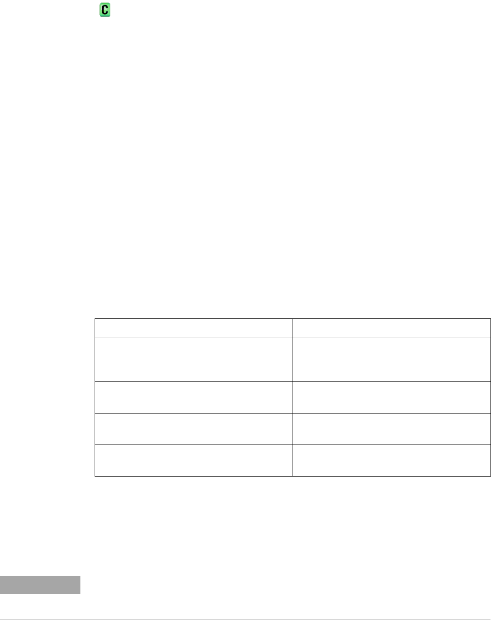
Oscilloscope Models Value and Mask Bit Assignments
4 analog + 16 digital channels (mixed-signal) Bits 0 through 15 - digital channels 0 through
15. Bits 16 through 19 - analog channels 1
through 4.
2 analog + 16 digital channels (mixed-signal) Bits 0 through 15 - digital channels 0 through
15. Bits 16 and 17 - analog channels 1 and 2.
4 analog channels only Bits 0 through 3 - analog channels 1 through 4.
Bit 4 - external trigger.
2 analog channels only Bits 0 and 1 - analog channels 1 and 2. Bit 4 -
external trigger.
NOTE
The optional source and the optional edge should be sent together or not at all. The edge
will be set in the simple pattern if it is included. If the edge source is also specified in the
mask, the edge takes precedence.