
User`s guide

98 5000 Series Oscilloscope User’s Guide
3 Triggering the Oscilloscope
When you connect an AutoProbe self-sensing probe, the
oscilloscope will automatically configure your probe to the
correct attenuation factor.
The probe correction factor must be set properly for
measurements to be made correctly.
Range The input voltage range can be set to 1.0 Volts or 8.0
Volts. When in current mode, the range is fixed at 1.0 Amps.
Range is automatically scaled according to the probe’s
attenuation factor.
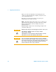
Maximum input voltage for the external trigger input of the
2-channel oscilloscope:
CAUTION
Maximum input voltage for external trigger (2-channel oscilloscopes)
CAT I 300 Vrms, 400 Vpk; transient overvoltage 1.6 kVpk
CAT II 100 Vrms, 400 Vpk
with N2863A 10:1 probe: CAT I 600 V, CAT II 300 V (DC + peak AC)
with 10073C 10:1 probe: CAT I 500 Vpk, CAT II 400 Vpk
CAUTION
Do not exceed 5 Vrms in 50 Ω mode. Input protection is enabled in
50 Ω mode and the 50 Ω load will disconnect if greater than 5 Vrms is
detected. However the input could still be damaged, depending on the
time constant of the signal. The 50 Ω input protection mode only
functions when the oscilloscope is powered on.