
User`s guide

52 5000 Series Oscilloscope User’s Guide
2 Front-Panel Controls
Interpreting the display
The oscilloscope display contains acquired waveforms, setup
information, measurement results, and softkeys for setting up
parameters.
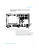
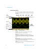
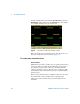
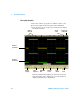
Figure 3 Interpreting the display
Status line The top line of the display contains vertical,
horizontal, and trigger setup information.
Display area The display area contains the waveform
acquisitions, channel identifiers, and trigger and ground level
indicators. Each channel’s information appears in a different
color.
Measurement line This line normally contains automatic
measurement and cursor results, but can also display advanced
trigger setup data and menu information.
Softkeys The softkeys let you set up additional parameters for
the selected mode or menu.
Channel
sensitivity
Delay
time
Trigger level
Trigger
source
Trigger
type
Run/Stop
mode
Sweep
speed
Channel
ground levels
Measurement
line
Softkeys
Trigger point,
time reference
Cursor
markers
defining
measurement
Status line
Trigger Level