
User`s guide

Getting Started 1
5000 Series Oscilloscope User’s Guide 35
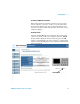
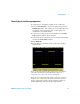
To connect the oscilloscope probes
Input impedance is selectable: 1 MΩ or 50 Ω. Press the channel
on/off key (see page 46), then press the Imped softkey to select
the input impedance.
The 1 MΩ mode is for use with many passive probes and for
general purpose measurements. The high impedance minimizes
the loading effect of the oscilloscope on the circuit under test.
The 50 Ω mode matches 50 Ω cables and some active probes
commonly used in making high frequency measurements. This
impedance matching gives you the most accurate measurements
since reflections are minimized along the signal path.
1 Connect the supplied oscilloscope probe to an oscilloscope
channel BNC connector on the front panel of the
oscilloscope.
2 Connect the retractable hook tip on the probe tip to the
circuit point of interest. Be sure to connect the probe ground
lead to a ground point on the circuit.
CAUTION
Maximum input voltage in 50 Ω mode
Do not exceed 5 Vrms at the BNC in 50 Ω mode on the Agilent 5000
Series oscilloscopes. Input protection is enabled in 50 Ω mode and the
50 Ω load will disconnect if greater than 5 Vrms is detected. However
the inputs could still be damaged, depending on the time constant of
the signal. The 50 Ω input protection mode on the Agilent 5000 Series
oscilloscopes only functions when the oscilloscope is powered on.
CAUTION
The probe ground lead is connected to the oscilloscope chassis and
the ground wire in the power cord. If you need to measure between
two live points, use a differential probe. Defeating the ground
connection and “floating” the oscilloscope chassis will probably result
in inaccurate measurements.