
User`s guide
Making Measurements 4
5000 Series Oscilloscope User’s Guide 165
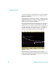
FFT Measurement
FFT is used to compute the fast Fourier transform using
oscilloscope input channels or math functions 1 + 2, 1 – 2, or 1 *
2. FFT takes the digitized time record of the specified source
and transforms it to the frequency domain. When the FFT
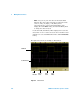
function is selected, the FFT spectrum is plotted on the
oscilloscope display as magnitude in dBV versus frequency. The
readout for the horizontal axis changes from time to frequency
(Hertz) and the vertical readout changes from volts to dB.
Use the FFT function to find crosstalk problems, to find
distortion problems in analog waveforms caused by amplifier
non-linearity, or for adjusting analog filters.
FFT Units
0 dBV is the amplitude of a 1 Vrms sinusoid. When the FFT
source is channel 1 or channel 2 (or channel 3 or 4 on 4-channel
models), FFT units will be displayed in dBV when channel units
is set to Volts and channel impedance is set to 1 MΩ.
FFT units will be displayed in dBm when channel units is set to
Volts and channel impedance is set to 50Ω.
FFT units will be displayed as dB for all other FFT sources or
when a source channel’s units has been set to Amps.
DC Value
The FFT computation produces a DC value that is incorrect. It
does not take the offset at center screen into account. The DC
value is not corrected in order to accurately represent
frequency components near DC.
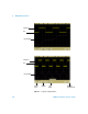
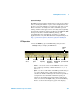
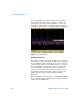
Aliasing
When using FFTs, it is important to be aware of frequency
aliasing. This requires that the operator have some knowledge
as to what the frequency domain should contain, and also
consider the sampling rate, frequency span, and oscilloscope