
User`s guide


26 Agilent Infiniium 90000 X-Series Oscilloscopes User’s Guide
2
Using the Oscilloscope
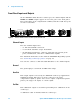
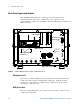
Front Panel Inputs and Outputs
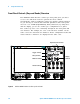
On the Infiniium 90000 X- Series oscilloscopes, the channel inputs and the
Aux Out and Cal Out outputs appear on the lower part of the front panel.
The ground plug, probe compensation terminal, and three USB host ports
are also located here.
Channel Inputs
The four channel inputs have:
• 3.5 mm threaded RF connectors.
• A convenient automatic torque mechanism.
• An AutoProbe II interface connector with pins that provide probe
power, identification, and other communication signals.
The AutoProbe II interface works with the InfiniiMax III probing system.
See “Connecting oscilloscope probes" on page 17.
You can also connect 3.5 mm threaded RF cables to the channel inputs.
Ground
The ground plug is convenient for ESD wrist straps.
Aux Out
This output signal is selected by the Infiniium oscilloscope application's
Calibration Output dialog box. It can be a DC level, the probe
compensation signal (a square wave used to adjust compensated passive
probes), the trigger out signal, or a demo signal.
Cal Out
This calibration output is used when performing user calibration on the
oscilloscope.
A calibration cable is included with the oscilloscope.
Figure 7 Infiniium 90000 X-Series Oscilloscope Front Panel I/O
$X[2XW &DO2XW