
User`s guide

20 Agilent Infiniium 90000 X-Series Oscilloscopes User’s Guide
1
Setting Up the Oscilloscope
Verifying basic oscilloscope operation
1
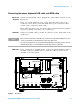
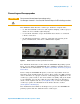
Install the supplied connector savers to each channel input. Agilent
recommends using the connector savers to protect the input connectors.
2
Connect one end of the 54916- 61626 calibration cable to oscilloscope
input channel 1.
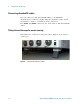
3
Connect the other end of the calibration cable to the Cal Out connector
on the front panel.
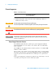
4
Press the [Default Setup] key on the front panel.
The display will pause momentarily while the oscilloscope is configured
to its default settings.
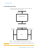
5
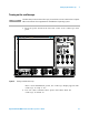
Press the [Auto Scale] key on the front panel.
The display will pause momentarily while the oscilloscope adjusts the
time/div setting and vertical scale. You should then see a square wave
with about four cycles on screen and a peak- to- peak amplitude of
approximately 4 divisions.
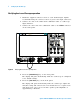
Figure 6 Verifying Basic Oscilloscope Operation
0 RGH 6RXUFH 6ORSH 6Z HHS
'HIDXOW
6HWXS
6HQVL
WLYLW\
&OHDU
'LVSOD\
0 XOWL
SXUSRVH
$XWR
6FDOH
=RRP
5XQ
6WRS
6LQJOH
0DUNHUV
7RX F K
$X[2XW &DO2XW
/HYH O
,QWHQVLW\
+RUL]RQWDO
5XQ&RQWURO
7ULJJHU
'LVSOD\0HDVXUH
9HUW LFDO
6HOHFW
3RVLWLRQ
3XVK WR7RJJOH
3XVK
IRU9HUQLHU
3XVK
IRU9HUQLHU
3XVK
IRU9HUQLHU
3XVK
WR&HQWHU
3XVK
WR&HQWHU
3XVK
WR=HUR
3 XVKIRU
(GJH
$GYDQFHG
$X[
$XWR
7U L J ¶ G
/RZ
+LJK
$XWR 7ULJ¶G$UP¶G
/LQ H
0 L[HG6LJQDO2VFLOORVFRSH
062;$
*6D V
*+]