
User`s guide

Setting Up the Oscilloscope
1
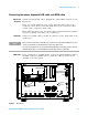
Agilent Infiniium 90000 X-Series Oscilloscopes User’s Guide 17
Connecting oscilloscope probes
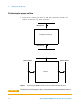
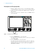
The Infiniium 90000 X- Series oscilloscope channel 1- 4 inputs have:
• 3.5 mm threaded RF connectors (like Agilent sampling oscilloscopes) to
ensure the most reliable signal integrity.
• A convenient automatic torque mechanism that ensures a consistent
8 in- lbs connection.
• An AutoProbe II interface connector with pins that provide probe
power, identification, and other communication signals.
The AutoProbe II interface works with the InfiniiMax III probing system.
There are four different InfiniiMax III probe amplifiers ranging from 16 to
30 GHz. For more information, see Agilent InfiniiMax III Probing System
Data Sheet.
Before using the InfiniiMax III probes, review the InfiniiMax III Probe
Handling Guide included with the probes. These probes are ESD sensitive
devices and there is a proper order for connecting probe amplifiers to the
oscilloscope, probe heads to the device under test (DUT), and probe heads
to the amplifier. You can also find the InfiniiMax III Probe Handling
Guide on the Agilent web site (www.agilent.com) or with other Agilent
oscilloscope probes documentation in the Probe Resource Center
(www.agilent.com/find/prc).
The N5442A Precision BNC 50
Ω
adapter lets you use the InfiniiMax II
probing system with the 90000 X- Series oscilloscopes.
CAUTION
Do not exceed the maximum input voltage rating.
Oscilloscope channels 1-4 are rated for maximum input of ±5V including transients.
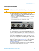
Figure 3 90000 X-Series Oscilloscope Probe Connectors