Agilent Infiniium 90000 X-Series Oscilloscopes User’s Guide s1
Notices © Agilent Technologies, Inc. 2013 Manual Part Number No part of this manual may be reproduced in any form or by any means (including electronic storage and retrieval or translation into a foreign language) without prior agreement and written consent from Agilent Technologies, Inc. as governed by United States and international copyright laws. 54916-97006 Edition April 30, 2013 Available in electronic format only Agilent Technologies, Inc.
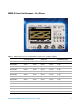
90000 X-Series Oscilloscopes—At a Glance Table 1 90000 X-Series Oscilloscope Bandwidths, Sample Rates, and Memory Depths Analog Bandwidth Sample rate 2 channel 4 channel 2 channel 4 channel 4 channel DSAX93204A 33 GHz 16 GHz 80 GS/s 40 GS/s 2 Gpts DSO/MSOX93204A 33 GHz 16 GHz 80 GS/s 40 GS/s 2 Gpts DSAX92804A 28 GHz 16 GHz 80 GS/s 40 GS/s 2 Gpts DSO/MSOX92804A 28 GHz 16 GHz 80 GS/s 40 GS/s 2 Gpts DSAX92504A 25 GHz 16 GHz 80 GS/s 40 GS/s 2 Gpts DSO/MSOX92504A 25 GHz 1
Ease of use with high performance The Agilent Technologies Infiniium oscilloscopes combine unprecedented ease- of use with high- performance digitizing oscilloscope functionality to simplify your design and analysis measurement tasks. • Traditional oscilloscope front- panel interface provides direct access to the controls needed for most troubleshooting tasks.
Trigger setup controls set mode and basic parameters • Select Edge, Glitch, or Advanced Modes. • Choose input source and slope. • Use graphical user interface to simplify configuration of pattern, state, delay, and violation trigger modes. • Use auxiliary trigger to increase triggering flexibility. Vertical controls set attenuation and position • Color- coded knobs make it easy to find the controls that affect each waveform.
In This Book This book gives you the information you need to begin using the Infiniium 90000 X- Series oscilloscopes. It contains three chapters, two appendixes, and an index: Chapter 1, “Setting Up the Oscilloscope,” starting on page 11 contains inspection, power requirements, air flow, and setup information.
Contents 90000 X-Series Oscilloscopes—At a Glance In This Book 3 6 1 Setting Up the Oscilloscope Inspecting package contents Environmental conditions 12 13 Positioning for proper airflow 14 Connecting the mouse, keyboard, LAN cable, and MSO cable Connecting power 15 16 16 16 Power Supply Protection Features Connecting oscilloscope probes 16 17 17 Connecting threaded RF cables 18 Tilting the oscilloscope for easier viewing Turning on the oscilloscope 18 19 Verifying basic oscilloscope opera
2 Using the Oscilloscope Front Panel Inputs and Outputs 26 Channel Inputs 26 Ground 26 Aux Out 26 Cal Out 26 Probe Compensation Terminal 27 USB Host Ports 27 Back Panel Inputs and Outputs 28 Motherboard I/O 28 USB Device Port 28 10 MHz In, 10 MHz Out 29 Trig Out 29 Aux Trig 29 Digital Channels Connector 29 Front Panel Controls (Keys and Knobs) Overview Graphical User Interface Overview Menu Overview 34 30 31 Setting the Oscilloscope to a Known Starting Condition Starting and Stopping Waveform Acquisition
Controlling the Display 51 Enabling or disabling the touch screen 51 Clearing the waveform display 51 Adjusting the brightness of the displayed waveform Saving and Printing Data 51 52 Forcing a Default Setup 53 Infiniium Hard Drive Recovery 53 3 Using the Online Help Accessing the online help 55 Navigating through the online help 57 Accessing context-sensitive information 57 A Safety Notices Warnings 59 Safety Symbols 60 B Working in Comfort About Repetitive Strain Injury 62 What is RSI? 62 W
Agilent Infiniium 90000 X-Series Oscilloscopes User’s Guide
Agilent Infiniium 90000 X-Series Oscilloscopes User’s Guide 1 Setting Up the Oscilloscope Inspecting package contents 12 Environmental conditions 13 Positioning for proper airflow 14 Connecting the mouse, keyboard, LAN cable, and MSO cable 15 Connecting power 16 Connecting oscilloscope probes 17 Connecting threaded RF cables 18 Tilting the oscilloscope for easier viewing 18 Turning on the oscilloscope 19 Verifying basic oscilloscope operation 20 Installing application programs on Infiniium 21 Changing Wind
1 Setting Up the Oscilloscope Inspecting package contents ✔ Inspect the shipping container for damage. • Keep the shipping container or cushioning material until you have inspected the contents of the shipment for completeness and have checked the oscilloscope mechanically and electrically. • If the shipping container is damaged, or the cushioning materials show signs of stress, notify the carrier and your Agilent Technologies Sales Office. Keep the shipping materials for the carrier’s inspection.
1 Setting Up the Oscilloscope Environmental conditions Table 2 90000 X-Series Oscilloscope Environmental Characteristics Environment Indoor use only. Temperature Operating: 5 °C to + 40 °C Non-operating: –40°C to +65 °C Humidity Operating: up to 95% relative humidity (non-condensing) at +40 °C Non-operating: up to 90% relative humidity at +65 °C Altitude Operating: up to 4,000 meters (12,000 feet) Non-operating: up to 15,300 meters (50,000 feet) Vibration Operating random: 00.
1 Setting Up the Oscilloscope Positioning for proper airflow 1 Position the oscilloscope where it will have sufficient clearance for airflow around the top, back, and sides. Minimum 0 mm Front panel of oscilloscope Minimum 0 mm Rear Panel Minimum 39 mm Minimum 100 mm Minimum 100 mm Top View Figure 1 C AU T I O N 14 Positioning the 90000 X-Series Oscilloscope with Sufficient Clearance Do not place the oscilloscope side-by-side with other instruments blowing warm air.
1 Setting Up the Oscilloscope Connecting the mouse, keyboard, LAN cable, and MSO cable Mouse and Keyboard A mouse and keyboard can be plugged into either USB host ports or the PS/2 ports. There are several USB host ports on the back and front panel of the oscilloscope that can be used. (The USB device port is used for remote control of the oscilloscope from a PC.) When using the PS/2 ports, the mouse and/or keyboard must be plugged in prior to turning on power to the oscilloscope.
1 Setting Up the Oscilloscope Connecting power Table 3 Power Requirements Power 100 - 240 VAC at 50/60 Hz Input power 800 Watts 1 Connect the power cord to the rear of the oscilloscope, then to a suitable AC voltage source. C AU T I O N Use only power cords designed for your oscilloscope. The line cord provided is matched by Agilent to the country of origin of the order. WA R N I N G NOTE To avoid electric shock, be sure the oscilloscope is properly grounded.
Setting Up the Oscilloscope 1 Connecting oscilloscope probes C AU T I O N Do not exceed the maximum input voltage rating. Oscilloscope channels 1-4 are rated for maximum input of ±5V including transients. The Infiniium 90000 X- Series oscilloscope channel 1- 4 inputs have: • 3.5 mm threaded RF connectors (like Agilent sampling oscilloscopes) to ensure the most reliable signal integrity. • A convenient automatic torque mechanism that ensures a consistent 8 in- lbs connection.
1 Setting Up the Oscilloscope Connecting threaded RF cables You can connect 3.5 mm threaded RF cables to the Infiniium 90000 X- Series oscilloscope inputs using the automatic torque “clutch” mechanism to ensure a consistent 8 in- lbs connection. The Aux Out and Cal Out connectors also work with 3.5 mm threaded RF cables. Tilting the oscilloscope for easier viewing Tabs under the oscilloscope's front feet can be flipped out to tilt the oscilloscope.
Setting Up the Oscilloscope 1 Turning on the oscilloscope NOTE The first time you turn on the oscilloscope, you must have a mouse connected to accept the Microsoft end-user license agreement for the Windows 7 operating system. 1 Press the power switch in the lower left corner of the oscilloscope front panel.
1 Setting Up the Oscilloscope Verifying basic oscilloscope operation 1 Install the supplied connector savers to each channel input. Agilent recommends using the connector savers to protect the input connectors. 2 Connect one end of the 54916- 61626 calibration cable to oscilloscope input channel 1. 3 Connect the other end of the calibration cable to the Cal Out connector on the front panel.
Setting Up the Oscilloscope 1 If you do not see the waveform, make sure your power source is adequate, the oscilloscope is properly powered on, and the probe is connected securely to the front- panel channel input and to the probe calibration output. 6 Move the mouse around the mouse surface and verify that the on- screen pointer follows the mouse movement.
1 Setting Up the Oscilloscope Changing Windows Operating System Settings NOTE Exit the oscilloscope application before changing any Windows operating system settings outside of the oscilloscope application. Many Windows operating system settings can be changed to suit your own personal preferences. However, some operating system settings should not be changed because doing so would interfere with the proper operation of the oscilloscope. • Do not change the Power Options.
1 Setting Up the Oscilloscope Turning off the oscilloscope 1 Press the power switch at the lower left corner of the oscilloscope front panel. The oscilloscope will go through a normal Windows operating system shutdown process. Cleaning the oscilloscope Clean the oscilloscope with a soft cloth dampened with a mild soap and water solution. C AU T I O N Do not use too much liquid in cleaning the oscilloscope. Water can enter the Infiniium front panel, damaging sensitive electronic components.
1 24 Setting Up the Oscilloscope Agilent Infiniium 90000 X-Series Oscilloscopes User’s Guide
Agilent Infiniium 90000 X-Series Oscilloscopes User’s Guide 2 Using the Oscilloscope Front Panel Inputs and Outputs 26 Back Panel Inputs and Outputs 28 Front Panel Controls (Keys and Knobs) Overview 30 Graphical User Interface Overview 31 Menu Overview 34 Setting the Oscilloscope to a Known Starting Condition 36 Starting and Stopping Waveform Acquisitions 37 Adjusting the Horizontal Time Scale and Trigger Position 38 Adjusting the Vertical Settings 41 Setting Up Triggers 44 Using Markers and Making a Measu
2 Using the Oscilloscope Front Panel Inputs and Outputs On the Infiniium 90000 X- Series oscilloscopes, the channel inputs and the Aux Out and Cal Out outputs appear on the lower part of the front panel. The ground plug, probe compensation terminal, and three USB host ports are also located here. $X[ 2XW Figure 7 &DO 2XW Infiniium 90000 X-Series Oscilloscope Front Panel I/O Channel Inputs The four channel inputs have: • 3.5 mm threaded RF connectors. • A convenient automatic torque mechanism.
Using the Oscilloscope 2 You can also use the Infiniium oscilloscope application’s Calibration Output dialog box (Utilities > Calibration Output) to select other output signals, just like you can for the Aux Out output. Probe Compensation Terminal This terminal has a square wave signal that is used to adjust compensated passive probes. Be sure to use an N5449A high- impedance adapter.
2 Using the Oscilloscope Back Panel Inputs and Outputs The Infiniium 90000 X- Series oscilloscope’s back panel has the motherboard I/O connectors, a USB device port, reference clock synchronization connectors, and BNC connectors. MSO models include an MSO connector. /$1 FRQQHFWRU $& SRZHU FRUG SOXJV LQWR KHUH /PO "VUP .
Using the Oscilloscope 2 10 MHz In, 10 MHz Out The 10 MHz In BNC connector is used to synchronize the oscilloscope's horizontal timebase system to a reference clock that you provide. The clock that you provide must meet the following specifications: • Amplitude: 178 mV peak to 1 V peak. • Frequency: 10 MHz ±5 ppm high- quality sine wave or square wave.
2 Using the Oscilloscope Front Panel Controls (Keys and Knobs) Overview The Infiniium 90000 X- Series oscilloscope front panel gives you direct access to the functions needed to perform the most common measurements, using a traditional oscilloscope interface. Knobs and keys let you directly set vertical and horizontal parameters. The front panel also has a set of LED (Light- Emitting Diode) indicators; by using these and the display, you see the oscilloscope’s configuration at a glance.
Using the Oscilloscope 2 Graphical User Interface Overview With the graphical interface for the Infiniium oscilloscope, you can access all the configuration and measurement features of the oscilloscope through an easy- to- use system of menus, toolbars, dialog boxes, icons, and buttons. The graphical interface is arranged so the most common functions affecting the waveform display are located around the edge of the waveform viewing area.
2 Using the Oscilloscope Waveform display area Ground reference indicator (icon on right) Figure 11 Infiniium Oscilloscope Waveform Display Area The waveform display area shows the waveforms and, optionally, the results of your measurements. Several display options, including a grid, are available. You can use the mouse to click and drag waveforms to new vertical or horizontal positions.
Using the Oscilloscope Adjust tab area size Horizontal reference indicators Single 2 Horizontal and Trigger toolbar See more measurements Turn off measurements Set horizontal scale Run Stop Clear display Print screen Set horizontal position (delay) Access the Horizontal Setup dialog box Access the Trigger Setup dialog box Set trigger level Tab display area Waveform brightness Figure 12 Infiniium Oscilloscope Bottom of Display The tab display area in the very bottom of the display shows informat
2 Using the Oscilloscope Menu Overview Menus are a part of the graphical user interface. You can use them to perform defined operations, set up measurement parameters, and access every function the oscilloscope provides.
2 Using the Oscilloscope Figure 13 Infiniium Oscilloscope Menus Look through the menus to get an overview of the many features and capabilities of your Infiniium oscilloscope. For example, the Demos menu selections include various demos that illustrate features of the scope.
2 Using the Oscilloscope Setting the Oscilloscope to a Known Starting Condition You can set up the oscilloscope for many different kinds of complex measurements. $XWR 6FDOH 'HIDXOW 6HWXS Figure 14 Setup Control Keys • To automatically configure the oscilloscope for the current input signal(s), press the [Auto Scale] key or select Control > Autoscale from the menu bar. • To reset the oscilloscope to its default setup, press the [Default Setup] key or choose Control > Default Setup.
2 Using the Oscilloscope Starting and Stopping Waveform Acquisitions Use the acquisition run controls to run and stop acquisitions or make a single acquisition. The highlighted area of the memory bar above the waveform display area shows how much of acquisition memory is displayed on the screen.
2 Using the Oscilloscope Adjusting the Horizontal Time Scale and Trigger Position Use the horizontal controls to configure the oscilloscope’s horizontal scale (time per division) and horizontal position of the waveform. You can also view a magnified section of the waveform using the zoom window. You can use the horizontal scale and position knobs, the horizontal GUI controls, or the Horizontal Setup dialog box to adjust the horizontal scale and position.
Using the Oscilloscope 2 • You can also use the controls in the horizontal and trigger toolbar to adjust the horizontal scale. Click the horizontal scale field to display a pop- up numeric keypad that lets you set a particular horizontal scale. • Or, you can use the two icons to the right. The left (smaller) icon shrinks the waveform, which decreases the horizontal scale and increases the time per division.
2 Using the Oscilloscope The horizontal scale and horizontal position controls now change how the waveform is shown in the delayed sweep window. The horizontal scale will change the amount of magnification, while the position will change the part of the waveform in the main window that is shown in the zoomed window. • Press the [Zoom] key again to turn it off.
Using the Oscilloscope 2 Adjusting the Vertical Settings Use the vertical controls to set the vertical scaling (volts per division) and vertical offset for each analog channel. You can also turn the display on or off for a particular channel.
2 Using the Oscilloscope Turning an analog channel on or off • To turn an analog channel on or off, press the channel number key or click the check box next to the channel number. When you turn off a channel, the current vertical scaling factor and scale buttons for that channel disappear. If you are not using a particular analog channel, you can turn it off to simplify the waveform display and increase the display update rate.
2 Using the Oscilloscope For Agilent Technologies probes that are compatible with AutoProbe II interfaces, the oscilloscope will automatically set these characteristics (except for skew) after identifying the probe when it is connected to the channel input. Turning digital channels on or off • To turn the digital channels on, click the check box next to the the right end of the toolbar.
2 Using the Oscilloscope Setting Up Triggers Use the trigger controls to set the conditions on which the oscilloscope will trigger and acquire an input signal. You can set up a variety of trigger conditions. Edge triggers and the parameters for edge triggering can be set up from the front panel.
Using the Oscilloscope 2 3 Press the [Sweep] key until the Trig’d or Auto (select one) LED is lit. When Trig’d is selected, the oscilloscope must find the trigger before saving and displaying captured data. When Auto is selected, if a trigger does not occur within a certain amount of time, an acquisition is automatically saved and displayed. In Auto trigger mode, you are able to see your signals while setting up the desired trigger.
2 Using the Oscilloscope Using Markers and Making a Measurement With the measurement controls you can display and adjust markers, define a key to perform automatic measurements or perform other quick actions, and make measurements.
2 Using the Oscilloscope horizontal reference point. When you make the measurement using drag- and- drop, the measurement uses the waveform feature closest to the point where you drop the icon. The most commonly used measurements are available on the toolbar. Others are available by selecting them from the Measure menu.
2 Using the Oscilloscope Channel numbers associate the measurement results with the channel waveform being measured. In some cases, geometric icons are also displayed to associate the measurement results with the location on the waveform being measured.
Using the Oscilloscope 2 The action taken when the [Multi Purpose] key is pressed depends on the feature selected in the Customize Multipurpose dialog box. The default feature is QuickMeas (quick measurements). • To turn on the quick measurement display, press the [Multi Purpose] key. The five preset measurements defined in the Quick Measurement configuration are enabled and results are displayed on the screen for the first waveform source.
2 Using the Oscilloscope • To turn on Marker B, push the Position knob until the marker you want to move appears in the pop- up dialog box. Marker B has a dashed line pattern on the waveform display. It is associated with the first available source on the display. • To move a marker, turn the Position knob. In Measurement Marker mode, the marker position cannot be changed.
2 Using the Oscilloscope Controlling the Display You can set the display to suit your preferences, such as by enabling the touch screen or adjusting the intensity of the displayed waveform. 'LVSOD\ &OHDU 'LVSOD\ 7RXFK ,QWHQVLW\ Figure 26 Display Control Keys and Knob Clear the waveform display Change the waveform brightness Figure 27 GUI Display Control Buttons Enabling or disabling the touch screen • Press the [Touch] key.
2 Using the Oscilloscope Saving and Printing Data • Choose File > Save from the menu bar to save your setup, composite, waveform, screen, or measurement data. • Press the Print Screen button in the Horizontal and Trigger toolbar to print the screen to the default printer configuration selected in the Windows Control Panel. • Choose File > Print from the menu bar to print waveform and setup data to a specified file. • You can also customize the [Multi Purpose] key to perform a QuickPrint.
2 Using the Oscilloscope Forcing a Default Setup If your Infiniium oscilloscope is not working properly when you start it up and pressing [Default Setup] does not fix the problem, follow these steps to force a default setup and return the Infiniium to normal operation. 1 Turn off the Infiniium. 2 Turn on the Infiniium. If the oscilloscope does not successfully restart then try recycling the power again. 3 After the Windows 7 load screen disappears, press the [Default Setup] key on the front panel.
2 54 Using the Oscilloscope Agilent Infiniium 90000 X-Series Oscilloscopes User’s Guide
Agilent Infiniium 90000 X-Series Oscilloscopes User’s Guide 3 Using the Online Help Accessing the online help 55 Navigating through the online help 57 Accessing context-sensitive information 57 Most of the information about using the Infiniium oscilloscope is included in the online help. The online help is accessible from the menu bar and from dialog boxes. This chapter explains how to use the help to find the information you need to use the oscilloscope effectively.
3 Using the Online Help Shows where the current topic is located in the table of contents Prints this topic on the default printer Closes the online help window Hides the view of the four tabs and left pane Figure 29 Online Help Home Page NOTE Viewing the Online Help Window The online help window will always stay on top of the interface display, so you can refer to it while working with the oscilloscope. You can move the window around the screen or resize it to make it easier to use.
Using the Online Help 3 Hyperlinks throughout the online help allow you to reach the information you need. Most hyperlinks are in blue underlined text, but some hyperlinks also have buttons (many of the reference topics) or tabs (in setup guide topics). You can find out whether an item has a hyperlink by pointing to it; if it is a hyperlink, the pointer will change to a hand icon. Clicking once will make a new topic appear.
3 58 Using the Online Help Agilent Infiniium 90000 X-Series Oscilloscopes User’s Guide
Agilent Infiniium 90000 X-Series Oscilloscopes User’s Guide A Safety Notices Warnings 59 Safety Symbols 60 This apparatus has been designed and tested in accordance with UL 61010- 1:2004 2nd Edition, and has been supplied in a safe condition. This is a Safety Class I instrument (provided with terminal for protective earthing). Before applying power, verify that the correct safety precautions are taken (see the following warnings).
A Safety Notices Safety Symbols Instruction manual symbol: the product is marked with this symbol when it is necessary for you to refer to the instruction manual in order to protect against damage to the product. Hazardous voltage symbol. Frame or chassis terminal symbol: Used to indicate a circuit common connected to grounded chassis.
Agilent Infiniium 90000 X-Series Oscilloscopes User’s Guide B Working in Comfort About Repetitive Strain Injury 62 Mice and Other Input Devices 63 To optimize your comfort and productivity, it is important that you set up your work area correctly and use your Infiniium oscilloscope properly. With that in mind, we have developed some setup and use recommendations for you to follow based on established ergonomic principles.
B Working in Comfort About Repetitive Strain Injury Because your comfort and safety are our primary concern, we strongly recommend that you use the Infiniium oscilloscope in accordance with established ergonomic principles and recommendations. Scientific literature suggests that there may be a relationship between injury to soft tissues—especially in the hands and arms—and prolonged improper use of keyboards or other equipment requiring repeated motions of the hands and forearms.
B Working in Comfort Mice and Other Input Devices Various aspects of using mice and other input devices may increase your risk of discomfort or injury. Observing the following recommendations may reduce that risk. • Try to keep your hand, wrist, and forearm in a neutral position while using your mouse or other input device. • If you use your thumb to rotate the ball on a trackball or spaceball, keep it in a relaxed, natural shape, and maintain a neutral posture in your hand, wrist, and forearm.
B 64 Working in Comfort Agilent Infiniium 90000 X-Series Oscilloscopes User’s Guide
Index A accessing index, 56 online help, 55 accessories and options, 12 acquisition starting and stopping, 37 adjusting analog channel’s vertical offset, 42 analog channel’s vertical scaling, 42 airflow requirements, 14 application software, 21 associating measurement results with waveforms, 46 Auto Scale key, 36 Autoscale, 20 B buttons, 30 as hyperlink, 57 help, 57 C calibration output, 20 cautions cleaning, 23 channel keys, 42 channels turning on or off analog channels, 42 checking the oscilloscope, 12
Index main timebase, 39 making measurements, 46 quick measurements, 48 waveform bigger or smaller, 42 markers and measurements, 46 moving, 50 positioning, 49 turning on or off, 49 measurement results associating with waveform, 46 measurement toolbar, 46 measurements, 46 and markers, 46 quick, 48 using markers, 49, 50 methods for accessing information, 55 Mode key, 44 mouse connecting, 15 verifying, 20 moving markers, 49, 50 waveform vertically, 42 MSO cable, 15 Multi Purpose key, 48 N navigating the onlin
Index associating with measurement results, 46 drag-and-drop measurements on, 46 making quick measurements, 48 measuring using markers, 49 turning off, 42 window zoom, 39 windows online help, 56 Windows operating system settings, 22 Z zoom display, 39 Zoom key, 39 Agilent Infiniium 90000 X-Series Oscilloscopes User’s Guide 67
Index 68 Agilent Infiniium 90000 X-Series Oscilloscopes User’s Guide