
Technical data


................
l- l
l- l
l-2
l-2
l-2
l-3
l-3
l-3
l-4
l-4
l-4
l-5
l-5
l-5
l-5
l-5
l-5
l-5
l-5
1-6
l-6
l-6
l-6
l-6
l-6
l-6
l-8
l-9
l-9
l-9
l-10
l-10
1-12
1-12
1-12
2-l
2-l
2-2
2-2
Contents-l
......................
Determining the HP-MSIB Address
........................
Addressing the Module
...........................
Preparation for Use
...........
2. Installation
Introduction
...............
Instrument Shipping Preparation Procedure.
...............
...............
...............
...............
...............
...............
...............
...............
...............
...............
...............
...............
...............
...............
...............
...............
...............
...............
...............
...............
...............
...............
...............
...............
...............
...............
...............
...............
...............
...............
...............
...............
...............
............
.
Packaging
.
......
Returning Instruments for Service
........
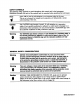
Static-Safe Accessories
..... .
Sales and Service Offices
......
Handling of Electronic Components
Test Equipment
.
Reducing ESD
Damage
.
Electrostatic Discharge Information
:
Mainframe/Module Interconnect
:
:
:
:
VIDEO ’
........
VIDEO OUT
........ .
VIDEO IN
LINEARAGC
21.4MHz
OUT
..........
21.4MHz
IN
..
..........
Rear-Panel Inputs and Outputs
..........
Module Latch
21.4-M&
.........
IF
0-1V
.......
VIDEO
.......
Front-Panel Outputs
........
ERR
(Error) LED
...
ACT (Active) LED
.....
Front-Panel Status Indicators
............
Front/Rear-Panel Features
..........
Accessories
....
Initial Inspection
..........
Manual Updating Supplement
........
Modules Covered by Manual
.... .
Serial Numbers
.........
Structural Terms
........ .
Safety Considerations
.
Functional Terms
.........
Modular Measurement System Terms
............
Module Description
General
Information
Introduction
Contents
1.