
Technical data
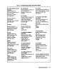


APC 3.5 connectors should be tightened to 5 to 8 inch-pounds.
The connector mounting threads will be damaged if more than 8 inch-pounds
of torque is applied.
2-6
Installation
SMA
and
70902A
should not be used to cascade the 21.4
MHz signal to another IF section. The power level is too low for this purpose.
Caution
All
lrri
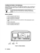
The AUX OUTPUT of the HP
Anafyzer
Rear-Panel Cables
Note
Figwe
2-4. HP 71210A Microwave Spectrum
70206A
HP-WI9
CABLES TO HP
SEC;:
ON
FREQUENCY
REFERENCE
LO
l/8
span cable.
PRESELECTED
RF SECT ION SEC:: ON
=
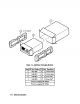
Connect the HP 70902A IF Section VIDEO OUT and the HP 70903A IF Section
VIDEO IN using a
l/8
span cable.
21.4MHz
INPUT using
a
21.4MIIz
OUTPUT and the HP 70902A IF
Section
3/8
span cable.
HP 70902A cable installation
n
Connect the HP 70903A IF Section
70993A
IF Section
VIDEO
OUT
and the HP 70900A LO VIDEO IN
using the
w
Connect the HP
7/8
span cable.
21.4MHz
INPUT using the
21.4MHz
OUTPUT and the HP 70903A IF Section
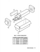
Rear-Panel Cabling for HP 71210A Microwave Spectrum Analyzer
Figure 2-4 depicts the rear-panel connections of an HP 71210A Microwave Spectmm Analyzer,
which includes both an HP 70903A and an HP 70902A. Using Table 2-2 for identification and
Figure 2-4 as an example, connect the IF rear-panel cables as described below.
HP 71210A Dual-IF Section Cable Connections
HP 70903A cable installation
n
Connect the RF section