
Technical data


Adbess Switches
Installation 2-3
J
ROW 2, COLUMN 18 ,
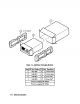
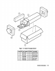
Figure 2-l.
Module
1
B
I
SWITCH SET T O
=
0= OF F
HP-MS
-l= ON
=
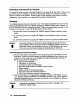
Setting the HP-MSIB Address Switches
A
module-address change requires the following steps:
1. Locate the address switches on the right side-panel of the module. See Figure 2-l for
an example of the switches.
2. Set the address switches labeled “row” to the binary value of the module ’s HP-MSIB
row number. For example, if the row value is 2, set the switches to binary 010 as
shown in Figure 2-l.
3. Set the five switches labeled “column ” to the binary value of the module ’s HP-MSIB
column number. For example, if the column value is 18, set the switches to binary
10010 as shown in Figure 2-l.
Note
3
Changing HP-MSIB addresses requires an
understanding
of
HP-MSIB
addressing rules. For information on determining and assigning HP-MSIB
addresses, refer to the installation and verification manual for the system
master (for example, HP 70900A Local Oscillator).
ROW
ADDRES S
MODULE ADDRES S