
Technical data


709OOA
Local Oscillator).
Installation 2-1
verification
manual
for the system master (for example, HP
mainframe/moduIe
interconnect. After the module is
installed, refer to Chapter 4 to ensure the module is operational.
Addressing and cabling examples in this chapter apply to both HP 71100A and HP 71210A
spectrum analyzers. For more detailed information about HP 70000 Modular Measurement
System configuration, cabling, and addressing, refer to the installation and
70903A
D? Section obtains both power and interface-bus
control through the module rear-panel
instaed, the HP
70900A
Local Oscillator).
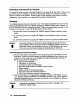
Preparation for Use
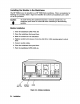
Installation of the module into an HP 70000 Modular Measurement System requires the
following steps:
n
Addressing the module
n
Installing the module in a mainframe
n
Connecting the rear-panel cables
When properly
HP-MSIB
addressing, refer to the installation and verification
manual for the system master (for example, HP
con&uration
and
70903A
in other HP 70000 Series
spectmm analyzers
The information presented is general in nature. For more detailed information on spectrum
analyzer
70903A
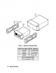
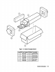
cabling requirements for either a
single or dual IF section configuration. Cabling for single- and dual-IF systems is shown in
Figure 2-3 and Figure 2-4, respectively. Depending on the number of IF sections required,
one of the two examples will apply when cabling the HP
Installation
Introduction
This chapter contains information needed to install the HP 70903A into an HP 70000 Series
mainframe and to configure and cable the HP 70903A for use in an HP 71100A or 71210A
spectrum analyzer. These examples cover the HP