
Technical data

dBm.
Module Latch
The module hex-nut latch secures the module in an HP 70000 Series mainframe. When the
module is being installed
or
removed from a mainframe, an 8 mm
hex-ball driver is used to
turn the module latch. Refer to Chapter 2 for information on module installation.
General Information l-5
21.4MHz
IF signal output of approximately
-15
21.4MHz
This BNC (m)
connector provides an auxiliary
fF
0-1V
video output.
0-1V
This BNC (m) connector provides an auxiliary
VfDEO
21.4MHz
input on the rear panel.
d.Bm,
is applied to
the
21.4MHz
signal, at a nominal level of -5
(Active)
LED
The green ACT LED active indicator of a slave module turns on when the module is making
a measurement and its master has keyboard control of the display. Refer to Chapter 5 for
additional detail related to ACT LED.
Note
The ACT LED of a slave module is only operative when there is a display in
the system or when the instmment is performing a self-test.
ERR (Error) LED
The red ERR LED lights when there is a problem (error) related to the module. Refer to
Chapter 5 for additional troubleshooting information.
Front-Panel Outputs
Note
3
The output levels described for both front- and rear-panels are typical and
only apply if a
Front/Rear-Panel Features
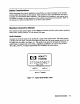
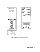
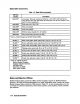
Figure l-2 shows the HP 70903A front- and rear-panel features.
Front-Panel Status Indicators
It is normal for both of the front-panel status LED indicators to flash on, then off, during the
module self-test. Self-test occurs each time the instrument is turned on. Listed below are
other reasons why each status LED might light.
ACT