About this Manual We’ve added this manual to the Agilent website in an effort to help you support your product. This manual is the best copy we could find; it may be incomplete or contain dated information. If we find a more recent copy in the future, we will add it to the Agilent website. Support for Your Product Agilent no longer sells or supports this product. Our service centers may be able to perform calibration if no repair parts are needed, but no other support from Agilent is available.
Installation and Veri cation Guide HP 70620B/70621A Preampli er ABCDE HP Part No. 70620-90036 Printed in USA February 1996 Edition A.0.
Notice The information contained in this document is subject to change without notice. Hewlett-Packard makes no warranty of any kind with regard to this material, including, but not limited to, the implied warranties of merchantability and tness for a particular purpose. Hewlett-Packard shall not be liable for errors contained herein or for incidental or consequential damages in connection with the furnishing, performance, or use of this material. Restricted Rights Legend.
Certi cation Hewlett-Packard Company certi es that this product met its published speci cations at the time of shipment from the factory. Hewlett-Packard further certi es that its calibration measurements are traceable to the United States National Institute of Standards and Technology, to the extent allowed by the Institute's calibration facility, and to the calibration facilities of other International Standards Organization members.
Safety Symbols The following safety symbols are used throughout this manual. Familiarize yourself with each of the symbols and its meaning before operating this instrument. CAUTION The CAUTION sign denotes a hazard. It calls attention to a procedure which, if not correctly performed or adhered to, could result in damage to or destruction of the product or the user's work. Do not proceed beyond a CAUTION sign until the indicated conditions are fully understood and met.
General Safety Considerations WARNING The instructions in this document are for use by quali ed personnel only. To avoid electrical shock, do not perform any servicing unless you are quali ed to do so. The opening of covers or removal of parts is likely to expose dangerous voltages. Disconnect the instrument from all voltage sources while it is being opened. The power cord is connected to internal capacitors that may remain live for ve seconds after disconnecting the plug from its power supply.
In This Book This book describes all of the installation procedures necessary to install and verify operation of your preampli er in an HP 70000 Series modular measurement system. (Refer to the HP 70000 Modular Spectrum Analyzer Installation and Veri cation Manual for system-level information.) Chapter 1, \General Information," describes the modules and their accessories, gives electrostatic discharge and packaging information, and lists Hewlett-Packard Sales and Service O ces.
Contents 1. General Information Safety Considerations . . . . . . . . . . . . . Initial Inspection . . . . . . . . . . . . . . . . Module Description . . . . . . . . . . . . . . Preampli er Modes . . . . . . . . . . . . . . Module Options . . . . . . . . . . . . . . . . Firmware Compatibility . . . . . . . . . . . . Examples of Con gurations Using Preampli ers . Front and Rear Panel Features . . . . . . . . . Status and Error LEDs . . . . . . . . . . . . Front-Panel Inputs and Outputs . . . . . . . .
4. Veri cation +28 VDC OUT Test . . . . . . . . . . . . . . . . . . . . . . . . . . . . . Manual Test . . . . . . . . . . . . . . . . . . . . . . . . . . . . . . . . Remote Test . . . . . . . . . . . . . . . . . . . . . . . . . . . . . . . . 5. Troubleshooting +28 VDC OUT Failure . . . . Front-Panel LEDs . . . . . . Error Messages . . . . . . . Usage/Operating Errors . . Hardware Warning Errors . Hardware-Broken Messages . Index Contents-2 . . . . . . . . . . . . . . . . . . . . . . . . . . . . .
Figures 1-1. Paths for Bypass and Preampli er Modes: HP 70620B (1 GHz to 26.5 GHz) . 1-2. Paths for Bypass and Preampli er Modes: HP 70620B Option 001 (100 kHz to 26.5 GHz) . . . . . . . . . . . . . . . . . . . . . . . . . . . . . . 1-3. Paths for Bypass and Preampli er Modes: HP 70621A (100 kHz to 2.9 GHz) . 1-4. HP 70620B and 70621A Front- and Rear-Panel Features . . . . . . . . . . 1-5. Static-Safe Work Station . . . . . . . . . . . . . . . . . . . . . . . . . 1-6. Typical Serial Number Label . . . . . .
1 General Information Safety Considerations Before operating this module, familiarize yourself with any safety markings on the module and the safety instructions in this manual. This module has been manufactured and tested according to international safety standards. However, to ensure safe operation of the module and personal safety of the user and service personnel, the cautions and warnings in this manual must be followed. Refer to the summary of safety considerations at the front of this manual.
Module Description The HP 70620B and HP 70621A preampli ers are 1/8-width modules designed to plug into an HP 70000 Series mainframe. The preampli ers are low-noise, high-gain ampli cation stages to use in front of the RF section of any HP 70000 Series RF or microwave spectrum analyzer. Refer to Table 1-1 for information about preampli er frequency ranges. Table 1-1. Frequency Ranges Preampli er HP 70620B Frequency Range 1 GHz to 26.5 GHz HP 70620B Option 001 100 kHz to 26.5 GHz HP 70621A 100 kHz to 2.
Preampli er Modes The preampli ers have two modes: preampli er and bypass. (See Figure 1-1, Figure 1-2, and Figure 1-3.) When used with the HP 70000 spectrum analyzer, the mode is \bypass." When the preampli er is used without the 70900 LO master module, it's default mode is preampli er on. Modes can be selected using either a softkey or a remote command. Information about using the softkey to select the mode is given below. Refer to the system master's Programming Manual for remote-operation information.
Module Options The HP 70620B and HP 70621A modules have the following module options available. Option 001 This option is available only for the HP 70620B. This option combines the HP 70621A capabilities with the HP 70620B capabilities, extending the module's low-end frequency range to 100 kHz. This results in a total frequency range of 100 kHz to 26.5 GHz. PIN diode switches allow full-band sweep.
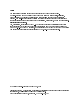
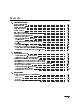
Examples of Con gurations Using Preampli ers The HP 70620B and HP 70621A preampli ers can be used in a variety of con gurations depending on your application needs. If overload or multiple responses are a concern, an HP 70600A or HP 70601A preselector can also be added to the system. Spur searching that involves a carrier signal requires a preselector to eliminate analyzer image and multiple responses.
Table 1-2.
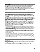
Front and Rear Panel Features Figure 1-4 shows the HP 70620B and HP 70621A front and rear panels. Status and Error LEDs Both of the front-panel LEDs ash on, then o again, during the module's self-test. Listed below are the other reasons for each LED to light. For troubleshooting information, refer to Chapter 5. ACT The ACT (active) LED lights when the module is being activated by an HP 70000 Modular System master that has an active keyboard link.
Figure 1-4.
Accessories The HP 70620B and HP 70621A preampli ers are available separately or as part of a precon gured system (which is assembled in a speci c con guration in the factory). Preampli ers in precon gured systems come with the RF cables that are needed for that speci c con guration. For a list of available system cables, refer to the Installation and Veri cation Manual for the system master.
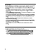
Preparing a Static-Safe Work Station Electrostatic discharge (ESD) can damage or destroy electronic components. Therefore, all work performed on assemblies consisting of electronic components should be done at a static-safe work station. Figure 1-5 shows an example of a static-safe work station. Two types of ESD protection are shown: a conductive table mat and wrist strap combination a conductive oor mat and heel strap combination Figure 1-5.
Preparing a Static-Safe Work Station Reducing ESD Damage To help reduce the amount of ESD damage that occurs during testing and servicing use the following guidelines: Be sure that all instruments are properly earth-grounded to prevent buildup of static charge. Personnel should be grounded with a resistor-isolated wrist strap before touching the center pin of any connector and before removing any assembly from a piece of equipment.
If You Need to Contact Hewlett-Packard Before calling Hewlett-Packard or returning your preampli er, please read your warranty information. Warranty information is printed at the front of this document. In any correspondence or telephone conversations, refer to the preampli er by its full model number and full serial number. With this information, the Hewlett-Packard representative can determine whether your unit is still within its warranty period.
Table 1-6. Hewlett-Packard Sales and Service O ces US FIELD OPERATIONS HEADQUARTERS Hewlett-Packard Company 19320 Pruneridge Avenue Cupertino, CA 95014, USA (800) 752-0900 California Hewlett-Packard Co. 1421 South Manhattan Ave. Fullerton, CA 92631 (714) 999-6700 Hewlett-Packard Co. 301 E. Evelyn Mountain View, CA 94041 (415) 694-2000 Colorado Hewlett-Packard Co. 24 Inverness Place, East Englewood, CO 80112 (303) 649-5000 Georgia Hewlett-Packard Co.
Returning Your Preampli er to Hewlett-Packard Hewlett-Packard has sales and service o ces around the world to provide complete support for your preampli er. To obtain servicing information or to order replacement parts, contact the nearest Hewlett-Packard sales and service o ce listed in Table 1-6. Use the following procedure to return your preampli er to Hewlett-Packard: 1. Fill out a service tag (available at the end of this service guide) and attach it to the instrument.
Table 1-7.
2 Installation This chapter contains information needed to con gure an HP 70620B or HP 70621A preampli er in an HP 70000 Modular Measurement System and then check basic module operation. Although the examples in this chapter show an HP 70620B, the same sequence can be used to con gure an HP 70621A in an HP 71100C system. For more detailed information about system con guration and addressing, refer to the Installation and Veri cation Manual for the system master (for example, HP 70900B).
Addressing the Module Modules need an appropriate Hewlett-Packard Modular System Interface Bus (HP-MSIB) address to be able to communicate with the master of the HP 70000 Modular Measurement System. The HP-MSIB address is set using the module's ROW and COLUMN address switches. Note The module can be used in most system con gurations without changing the factory-preset address.
Setting the HP-MSIB Address Switches The preampli er's address switches are located on the left side of the module. Table 2-1 gives the decimal value for each address switch when the switch is set to binary 1 (on). Table 2-1. Decimal Equivalents of Row and Column Address Switches Address Switch Decimal Value Row 3 2* 1* Column 4 2 1 5* 16 4 8 3 4 2* 2 1* 1 *These switches are factory-preset to binary 1 (on), resulting in an HP-MSIB address of 3, 19 (row 3, column 19).
Installing the Module in the Mainframe The preampli er module needs to be installed in an HP 70000 Modular Measurement System mainframe before it will operate. Follow the procedure below to install a module into the mainframe. See Figure 2-3 for identi cation of the module and mainframe parts called out in the procedure. 1. Turn the mainframe LINE switch o . 2. Open the mainframe front-panel door. 3. Slide the module into the mainframe. 4.
Figure 2-3.
Con guring an HP 70620B in an HP 71200C System The system shown in Figures 2-4 and 2-5 contains the following equipment. The preampli er is con gured in front of the RF section, as shown in Table 1-2, example A. HP 70620B Preampli er HP 71200C Microwave Spectrum Analyzer, which consists of the following: HP 70001A Mainframe HP 70004A Display HP 70310A Precision Frequency Reference HP 70900B Local Oscillator HP 70902A IF Section HP 70905A RF Section Figure 2-4.
Connect the HP 70620B RF OUTPUT to the HP 70905A RF INPUT using an SMA (f) to Type N (m) cable (HP part number 5022-0003). Figure 2-5 illustrates the cable connection. Figure 2-5.
Con guring an HP 70620B in an HP 71210C System The system shown in Figures 2-6 and 2-7 contains the following equipment. The preampli er is con gured in front of a preselector (the HP 70908A is a preselected RF section), as shown in Table 1-2, example B.
Connect the HP 70620B RF OUTPUT to the HP 70908A RF INPUT using a SMA (f) to Type N (m) cable (HP part number 5021-9952). Figure 2-7 illustrates the cable connection. Figure 2-7.
Con guring an HP 70620B in an HP 71200C Option 002 System The system shown in Figures 2-8 and 2-9 contains the following equipment. The preampli er is con gured between the preselector and the RF section, as shown in Table 1-2, example C.
Figure 2-9 illustrates the cable connections. Use the following steps to connect the preampli er: Connect the HP 70620B RF OUTPUT to the HP 70905B RF INPUT using an APC-3.5 (f) to SMA (m) cable (HP part number 5022-0064). Connect the HP 70620B RF INPUT to the HP 70600A RF OUTPUT using an APC-3.5 (f) to SMA (m) cable (HP part number 5022-0064). Figure 2-9.
Checking Module Operation The operation of the preampli er in an HP 70000 Modular Spectrum Analyzer system is checked by examining the front-panel LEDs, checking for error messages after the module's power-on self-test has run, and measuring the +28 VDC OUT voltage. Examining the Front-Panel LEDs The power-on self-test runs automatically when power is rst applied to the module. The front-panel LEDs ash on and then o during the self-test. Immediately after the self-test has run, the ERR LED should be o .
3 Speci cations This chapter contains module speci cations and characteristics for the HP 70620B and HP 70621A preampli ers. For system speci cations, refer to the system master's Installation and Veri cation Manual. This chapter contains both speci cations and characteristics. Characteristics are in italics and are identi ed with the word characteristic.
Module Speci cations and Characteristics +28 VDC OUT The +28 VDC OUT connector is a BNC (f) in both HP 70620B and HP 70621A modules. Output Voltage while in \On" state, 60 mA . . . . . . . . . . . . . . . . . . . . . . . . . . . . . . . +28 V dc 60.1 V dc while in \O " state . . . . . . . . . . . . . . . . . . . . . . . . . . . . . . . . . . . . . . . . . . . . . . . . . . . . . . <1 V RF OUTPUT The RF OUTPUT connector is an APC-3.5 (m) in the HP 70620B and an SMA (f) in the HP 70621A.
Bypass Insertion Loss (characteristic) Applies only when module is in bypass mode. HP 70620B 0 Hz to 2.9 GHz . . . . . . . . . . . . . . . . . . . . . . . . . . . . . . . . . . . . . . . . . . . . . . . . . . . . . . 1 dB 2.9 GHz to 12.7 GHz . . . . . . . . . . . . . . . . . . . . . . . . . . . . . . . . . . . . . . . . . . . . . . . . 1.8 dB 12.7 GHz to 26.5 GHz . . . . . . . . . . . . . . . . . . . . . . . . . . . . . . . . . . . . . . . . . . . . . . . 2.5 dB HP 70620B Option 001 0 Hz to 2.9 GHz . . .
RF INPUT The RF INPUT connector is an APC-3.5 (m) in an HP 70620B and a Type N (f) in an HP 70621A. Maximum safe input power (characteristic) Preampli er mode . . . . . . . . . . . . . . . . . . . . . . . . . . . . . . . . . . . . . . . . . +20 dBm (100 mW) Bypass mode . . . . . . . . . . . . . . . . . . . . . . . . . . . . . This is speci c to the RF section in the system. Refer to the appropriate RF section Installation and Veri cation Manual. Maximum dc input HP 70620B . . . . . . . . . . . . . . . . . .
General Speci cations and Characteristics Temperature Operation . . . . . . . . . . . . . . . . . . . . . . . . . . . . . . . . . . . . . . . . . . . . . . . . . . . . . . . 0 C to +55 C Storage . . . . . . . . . . . . . . . . . . . . . . . . . . . . . . . . . . . . . . . . . . . . . . . . . . . . . . 040 C to +75 C Weight (characteristic) HP 70620B . . . . . . . . . . . . . . . . . . . . . . . . . . . . . . . . . . . . . . . . . . . . . . . . . . . . . . . . 1.8 kg (4 lb) HP 70620B Option 001 . . . . .
4 Veri cation This chapter contains the test necessary to verify the +28 VDC OUT voltage speci cations. The system-level performance speci cations for the preampli er are in the Installation and Veri cation Manual for the system master (for example, HP 70900B Local Oscillator). System-level testing of systems controlled by an HP 70900 local oscillator can be accomplished in two ways: Run the system operation-veri cation tests, using revision C.00.01 or greater.
+28 VDC OUT Test Use either the manual or remote test to verify that the preampli er's +28 Vdc noise-source drive voltage meets speci cations. Refer to Table 4-1 for equipment requirements. Table 4-1. Equipment Requirements for +28 VDC OUT Test Equipment Voltmeter Requirements HP Model or Part Number accuracy better than 0.
5 Troubleshooting This chapter contains information about HP 70620B and HP 70621A front-panel LEDs and a listing of the error codes for the HP 70620B and HP 70621A. The information in this chapter is designed to help determine whether an error is being caused by the preampli er (HP 70620B or HP 70621A). For more detailed preampli er troubleshooting information, refer to the HP 70620B/HP 70621A Preampli er Service Manual.
Error Messages An error message usually consists of the model number of the a ected module, an error code, and the module HP-MSIB address. The error codes generated by the preampli ers (HP 70620B and HP 70621A) are listed below in numerical order. For a complete list of all system error messages, refer to the Installation and Veri cation Manual for the system master. Error Types Error Numbers Usage/Operating . . . . . . . . . . . . . . . . . . . . . . . . . . . . . . . . . . . . . . . . . . . . . . . .
Index A accessories adapter, 1-9 cables, 1-9 noise source, 1-9 ACT LED, 1-7 address map, 2-2 address switches decimal value, 2-3 location, 2-3 setting, 2-3 application examples, 1-5 B bypass mode, 1-3 C con guration examples, 1-5 E electrostatic discharge (ESD), 1-10 ERR LED, 1-7 error codes, 5-2 error lights, 1-7, 5-1 ESD (electrostatic discharge), 1-10, 1-11 F frequency range, 1-2 H HP 70620B frequency range, 1-2 inputs and outputs, 3-2 HP 70621A frequency range, 1-2 inputs and outputs, 3-2 HP-