TEP Color LCD Retrofit Kit for the HP 85662A Display Installation and User Guide Test Equipment Plus Tel: (360) 263-5006 Fax: (360) 263-5007 35707 NE 86th Ave., La Center, WA, USA 98629 800-260-TEST www.testequipmentplus.com © 2006 Test Equipment Plus. All Rights Reserved. HP is a registered trademark of Agilent Technologies Inc. National Instruments® is a registered trademark of National Instruments Corp. Parlex is a registered trademark of Parlex Corp.
©Copyright 2006 Test Equipment Plus All rights reserved. Publication Number 85662A-M5-1.10 2nd edition, December 2006 Printed in U.S.A. Reproduction, adaptation, or translation without prior written permission is prohibited, except as allowed under the copyright laws. Warranty The information contained in this manual is subject to change without notice.
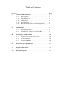
Table of Contents Section Page I General Information . . . . . . . . . . . . . . . . . . . . . . . . 1 1-1 Description . . . . . . . . . . . . . . . . . . . . . . . . . . 1 1-13 Specifications . . . . . . . . . . . . . . . . . . . . . . . . 1 1-15 Calibration . . . . . . . . . . . . . . . . . . . . . . . . . . .1 1-17 Adjustments . . . . . . . . . . . . . . . . . . . . . . . . . .1 1-19 Recommended Tools and Equipment . . . . . . 2 II Installation . . . . . . . . . . . . . . . . . . . . . . . . . . . . . .
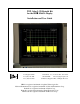
Section I 1-1 1-2 1-3 1-4 1-5 1-6 1-7 1-8 1-9 1-10 1-11 1-12 General Information Description The 8566/8567/8568 Color LCD Retrofit Kit is a drop-in replacement for the monochrome CRT in the HP 85662A display. The Retrofit Kit uses a state-ofthe-art Sharp 6.4” TFT color LCD with a resolution of 640 x 480 pixels. The intensity adjustment works as before; adjust the front panel intensity knob as you would for the CRT. The front panel align adjustment is no longer used.
1-19 1-20 Recommended Tools & Equipment The LCD kit installation will require the items listed in Table 1-1. Substitutions must meet the critical specifications listed in the table.
Section II Installation 2-1 2-2 Initial Inspection. Refer to table 5-1 for a list of parts included in the 85662A-LCD Retrofit Kit. Verify that all parts listed are included in your kit. 2-3 2-4 Installation of the Color LCD Kit. Installation should not be attempted unless it is done so by a highly skilled electronic repair technician. Kit installation time is approximately 3 hours. Refer to spectrum analyzer service manual for location of assemblies. Disconnect AC power cord.
2-14 2-15 2-16 2-17 2-18 2-19 2-20 2-21 2-22 2-23 2-24 2-25 2-26 2-27 2-28 2-29 2-30 2-31 2-32 2-33 2-34 Disconnect the two 14-pin DIP ribbon cable connectors from the motherboard sockets by spreading the retainer clips and pulling the DIP connectors free. Disconnect the 50-pin ribbon cable connector from the top edge of the A1A1 keyboard. Set the front panel assembly aside. NOTE: The following steps refer to the A1A4 and A1A5 video driver boards.
2-35 2-36 2-37 2-38 2-39 Nibble out the third from the top ½” by ⅛” card cage bar on the side of the A3A4 card cage facing the CRT to make a routing path for the A3A4 W2 cable. File smooth any sharp edges caused by the nibbling (figure 2). Replace the A3 card cage and all its cards except for the old A3A4 card.
2-40 2-41 2-42 2-43 2-44 2-45 Solder a 2” wire (W7 included in kit) between A3XA2P2 pin 27 and A3XA4P1 pin 6 on the underside of the A3 motherboard (figure 3). Solder a 2” wire (W8 included in kit) between A3XA2P2 pin 23 and A3XA4P1 pin 24 (figure 3). Route the shorter 6.3” coax cable (W5 included in kit) under the 50-pin ribbon cable and solder the center conductor to A3XA4P1 pin-7 and the shield to A3XA4P1 pin-25.
2-46 2-47 2-48 2-49 De-solder and discard the eight L-shaped pins that the CRT plugged into (figure 4) on the motherboard. NOTE: This step is required because the pins no longer have a mating CRT connector that is insulated and so they would be a potential shorting hazard to the instrument cover. Solder the yellow wire on the 23V power cable (W3 included in kit) to connector A1XA6 pin-7 on the bottom of the A1 motherboard (figure 4).
2-58 2-59 2-60 2-61 2-62 2-63 2-64 2-65 2-66 2-67 2-68 2-69 2-70 2-71 2-72 2-73 2-74 2-75 Remove the keyboard assembly from the old inner bezel casting (figure 5) and transfer it to the modified inner bezel casting provided in the kit. Replace the eight 4-40 flat-head screws on the front of the keyboard assembly. Replace the front panel keyboard overlay, retaining nuts, “Level” knob, and “Intensity” knob. Remove the two small screws from the bottom of the plastic CRT bezel.
2-76 2-77 2-78 2-79 2-80 2-81 2-82 2-83 2-84 2-85 2-86 2-87 2-88 2-89 Re-route the 14-pin DIP ribbon cable from the keyboard (that used to go to the motherboard A1J1) to the LCD Kit’s A1A21 Plotter board socket labeled “FRONT PANEL” (figure 6). Connect the 14-pin DIP ribbon cable (W6 included in the kit) to the motherboard A1J1, observing polarity. The W6 ribbon should come off the forward side of the connector, AND pin-1 should go towards the left as viewed from the front.
Section III Principles of Operation 3-1 3-2 3-3 A3A4 Color Video Processor. The A3A4 color video board uses a dual-access memory array. This allows simultaneous use of the video memory by the 85662A data and control bus as well as the color video processor (A3A4U2) that changes the video from monochrome to color and formats the information into a compressed data stream. For sweep times of ≤10 milliseconds (fast sweep), the A3A4 digitizes the fast sweep data that comes in as analog-X and -Y signals.
Section IV Fast Sweep Adjustments 4-1 4-2 4-3 4-4 4-5 4-6 4-7 4-8 4-9 4-10 4-11 4-12 4-13 4-14 4-15 4-16 4-17 4-18 4-19 Allow 30 minutes warm up of spectrum analyzer before adjustments. Enter CENTER FREQUENCY 1 GHz, FREQUENCY SPAN 0 Hz, scale LINEAR, trigger VIDEO, SWEEP TIME 20 msec. Apply a 1GHz signal, 0dBm, and pulsed with a 500Hz square wave to the spectrum analyzer RF input. Enter REFERENCE LEVEL and adjust front panel RPG for full-scale deflection on LCD. Enter SWEEP TIME 10 msec.
Section V Replaceable Parts 5-1 This section contains information for ordering replacement parts found in table 5-1.
Section VI Block Diagram 85662A System Bus A3XA4P1 edge connector Fast Sweep X, Y, FS, LRTRC TEP A3A4 Color Video Processor & Fast Sweep Capture +23V, PWDN signal Color Scheme Select (focus pot) & Intensity TEP A1A21 andAnd Plotter LCD Backlight Inverter Backlight Drive TEP A1A22 Dual Page SRAM TEP A1A23 Sharp® 6.