
Instruction manual


Chapter 2 Service
Troubleshooting the Counter
Assembly-Level Service Guide 2-45
2
Troubleshooting the Counter
Power Supply Check
WARNING HAZARDOUS VOLTAGES ARE ON THE POWER SUPPLY ASSEMBLY.
ONLY SERVICE TRAINED AND QUALIFIED PERSONNEL SHOULD
PERFORM THE FOLLOWING PROCEDURE.
1 Remove the power cord from the back of the instrument to disconnect the
Counter from the power source.
2 Remove the cover as described in Chapter 3.
NOTE A4 AC Power Supply Assembly is fused for safety reasons. It is assumed that if the
fuses are blown, then damage has occurred to the power supply which will make it
unreliable. Do not attempt to repair the power supply.
3 Connect the Counter to the power source.
The fan should begin to operate as soon as power is supplied. If the fan does not
operate, replace A4 AC Power Supply Assembly.
Refer to Chapter 3, “Replacing Assemblies,” in this service guide if you need to
remove or replace an assembly.
After replacing the power supply assembly, perform the appropriate calibration
procedures in this chapter.
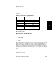
4 Connect the negative lead of a voltmeter to the chassis and verify that the
voltages in Table 2-4 match the voltages measured on connector J18 of A1
Motherboard Assembly. See Figure 2-9 for illustration of J18 viewing from the
bottom of the Counter.
CAUTION BE CAREFUL to NOT short the positive-side lead of the voltmeter to the chassis
when probing at the testpoints shown in Figure 2-9.