About this Manual We’ve added this manual to the Agilent website in an effort to help you support your product. This manual is the best copy we could find; it may be incomplete or contain dated information. If we find a more recent copy in the future, we will add it to the Agilent website. Support for Your Product Agilent no longer sells or supports this product. Our service centers may be able to perform calibration if no repair parts are needed, but no other support from Agilent is available.
Installation and Service Guide Publication number 16500-97012 First edition, April 1995 For Safety information, Warranties and Regulatory information, see the pages behind the index Copyright Hewlett-Packard Company 1993, 1994, 1995 All Rights Reserved HP 16500H Interface Module
In This Book This book shows you how to install and service the HP 16500H Interface Module . This book contains the following chapters: • Chapter 1 provides and overview of the HP 16500H. • Chapter 2 shows you how to install the HP 16500H in the HP 16500B mainframe. This chapter also provides information on where to go next, depending on which environment you are using the HP 16500 system in. • Chapter 3 contains the procedures for performance verification and replacing assemblies.
Contents 1 Introducing the HP 16500H Interface Module Accessories Supplied 1–3 Requirements 1–3 Physical Connections 1–3 LAN Support 1–4 2 Installing the Interface Module To Install the HP 16500H Hardware 2–2 To Verify the Installation 2–4 Ethernet LAN Interface 2–5 HP 16501A Expansion Frame Interface 2–7 HP 16505A Protoytype Analyzer 2–8 3 Servicing the Interface Module Verify the Interface Module Performance 3–2 Troubleshooting an HP 16501A Expansion Frame 3–7 Troubleshooting in an Ethernet LAN Environ
Contents-2
1 Introducing the HP 16500H 1-2 Accessories Supplied 1–3 Requirements 1–3 Physical Connections 1–3 LAN Support 1-4 Introducing the HP 16500H Interface Module
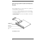
Introducing the HP 16500L LAN Interface Module The HP 16500H LAN interface module provides three capabilities for your HP 16500 Logic Analysis System: • connection to an Ethernet 10Base-T Local Area Network (LAN) • connection to an HP 16501A Expansion Frame for the HP 16500B Logci Analysis System • a high-speed port for connecting the HP 16500B to an HP 16505A Prototype Analyzer Expander Frame connector Ethertwist LAN connector High-speed port The HP 16500H interface module 1–2
Introducing the HP 16500H Interface Module Accessories Supplied Accessories Supplied The HP 16500H is shipped with the following accessories: • • • • this Installation and Service Guide a LAN Administrator’s and Service Guide a LAN User’s Guide screws and one cable to install the HP 16500H into the HP 16500B mainframe • TORX 10 and TORX 15 wrenches If your HP 16500H was installed into the HP 16500B by HP, you will not receive these tools.
Introducing the HP 16500H Interface Module LAN Support LAN Support For information about the LAN protocols and file types supported by the HP 16500H, refer to the LAN Administrator’s and Service Guide 1–4
2 This chapter includes procedures to install the interface module into the HP 16500B Logic Analysis System mainframe and to verify the installation. For detailed information on how to install the HP 16500B in one of the three applications supported by the interface module, refer to the documentation for the specific application. This chapter provides references to those other documents.
Installing the Interface Module To Install the HP 16500H Hardware To Install the HP 16500H Hardware If you need instructions for removing and replacing parts of the HP 16500B, refer to the HP 16500B Logic Analysis System Service Guide. WARNING CAUTION SHOCK HAZARD Disconnect the power from the mainframe before performing the following procedures.
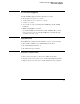
Installing the Interface Module To Install the HP 16500H Hardware 3 Slide the interface module into the mainframe through the slot in the rear panel. 4 Install the screws connecting the interface module to the mainframe. Two screws through the top of the interface module connect it to the sheetmetal plate, and four screws through the rear plate of the interface module connect it to the rear panel of the mainframe. 5 Connect the 80-pin cable to the CPU board and to the interface module.
Installing the Interface Module To Verify the Installation To Verify the Installation 1 Check that "Ethernet" is available in the Communications menu of the mainframe System Configuration menu. When you power-up the mainframe, the Logic Analysis System performs the power-up self-tests. After the self-tests are finished, the screen displays the System Configuration menu. If the operating system finds an interface module installed, then Ethernet is available in the Communications menu.
Installing the Interface Module Ethernet LAN Interface Ethernet LAN Interface The LAN interface provides a network-based interface between the HP 16500B Logic Analysis System and personal computers and workstations over a 10Base-T Ethernet LAN. Detailed information on installing and troubleshooting in the LAN environment is covered in the HP 16500H LAN Administrator’s and Service Guide. The following steps are an overview of the process with some troubleshooting hints.
Installing the Interface Module Ethernet LAN Interface 3 Verify connectivity with an echo request. In most network environments, an echo request is accomplished using the ping utility. For the exact syntax for the ping or other echo request utility, refer to your network documentation. A normal response to multiple echo requests is 9, 10, or possibly 11 packets transmitted for every 10 echo requests. If there is no response to the echo request, first check the command line.
Installing the Interface Module HP 16501A Expansion Frame Interface HP 16501A Expansion Frame Interface The interface port for the HP 16501A Expansion Frame permits you to quickly and easily connect an expansion frame to the HP 16500B mainframe. With an expansion frame connected to the mainframe, a total of ten 16500-series measurement modules can be configured and utilized.
Installing the Interface Module HP 16505A Protoytype Analyzer HP 16505A Protoytype Analyzer The high-speed interface port for an HP 16505A Protoytype Analyzer permits you to connect a Prototype Analyzer to the HP 16500B mainframe. Detailed installation information is covered in the HP 16505A Prototype Analyzer Installation Guide.
3 Verifying the Interface Module Performance 3-2 Performance verification procedure 3-3 Troubleshooting an HP 16501A Expansion Frame 3-7 Troubleshooting in an Ethernet LAN Environment 3-8 Troubleshooting in the HP 16505A Prototype Analyzer Environment 3-9 Removing and Replacing the HP 16500H Interface Module 3-10 Returning Parts 3-13 Ordering Replacable Parts 3-14 Replacable Parts 3-15 Servicing the Interface Module
Servicing the Interface Module Verify the Interface Module Performance Verify the Interface Module Performance Before starting the interface module performance verification, check all cables and connectors to ensure that all cables are properly connected. The interface module performance verification (self-test) is divided into two sections. The first section tests the physical connection, for example, the cable and termination.
Servicing the Interface Module Verify the Interface Module Performance Procedure This procedure verifies the performance of the interface module. To verify performance of the HP 16500B Logic Analysis System or the optional measurement modules, refer to the Service Guides for those products. 1 If the screen appears blank, the interface module or cable may be defective. a Remove power from the HP 16500B, disconnect the power cable, then remove the top cover.
Servicing the Interface Module Verify the Interface Module Performance If the "Ethernet" selection appears in the Communications menu, then go to step 5. If "Ethernet" does not appear in the Communications menu, perform the following steps. a Remove power from the HP 16500B, disconnect the power cable, then remove the top cover. b Remove and inspect the interface module cable for signs of damage. If the cable appears defective, replace it.
Servicing the Interface Module Verify the Interface Module Performance 6 Touch Test System, then select Mainframe Test in the pop-up menu. The screen will display the Mainframe Test menu. 7 Select Option Board Test, then select Run. If an HP 16501A expansion frame is not connected, then expect a "No Expansion Card Present" message to appear when you run the Option Board Test. Refer to the HP 16500B/16501A Service Guide for more information about the expansion frame.
Servicing the Interface Module Verify the Interface Module Performance 8 Verify that the tests pass. If all of the tests pass, then go to the step 9. If any of the tests fail, then LAN hardware or the interface module is suspect. • To verify the LAN hardware, perform the following checks: Check that the LAN cable is properly seated at both the interface module and at the client/server/router ends. Check that the LAN cable is good and that all signal lines in the cable have electrical integrity.
Servicing the Interface Module Troubleshooting an HP 16501A Expansion Frame Troubleshooting an HP 16501A Expansion Frame For details on troubleshooting a system that is connected to an HP 16501A Expansion Frame, refer to the HP16500B/16501A Logic Analysis System Service Manual. If you suspect that the HP 16500H Interface Module is defective, use the procedures in this chapter to verify the interface module performance and, if necessary, replace the hardware.
Servicing the Interface Module Troubleshooting in an Ethernet LAN Environment Troubleshooting in an Ethernet LAN Environment For details on troubleshooting a system that is connected to an Ethernet LAN, refer to the HP16500H LAN Administrator’s and Service Guide. If you suspect that the HP 16500H Interface Module is defective, use the procedures in this chapter to verify the interface module performance and, if necessary, replace the hardware.
Servicing the Interface Module Troubleshooting in the HP 16505A Prototype Analyzer Environment Troubleshooting in the HP 16505A Prototype Analyzer Environment For details on troubleshooting a system that is connected to an HP 16505A Protoype Analyzer, refer to the HP16505A Prototype Analyzer Service Guide. If you suspect that the HP 16500H Interface Module is defective, use the procedures in this chapter to verify the interface module performance and, if necessary, replace the hardware.
Servicing the Interface Module Removing and Replacing the HP 16500H Interface Module Removing and Replacing the HP 16500H Interface Module 1 If the HP 16500B Logic Analysis System is connected and mounted to a LAN, then unmount the HP 16500B file system. Unmounting from a LAN You must unmount the HP 16500B before power is removed from it. Then, you can mount the HP 16500B 15 seconds after the System Configuration menu is displayed when powering up the instrument.
Servicing the Interface Module Removing and Replacing the HP 16500H Interface Module 5 Remove the screws connecting the interface module to the mainframe. Two screws through the top of the interface module connect it to the sheetmetal plate, and four screws connect the rear plate of the interface module to the rear panel of the mainframe (see the figure below).
Servicing the Interface Module Removing and Replacing the HP 16500H Interface Module 6 Install the new interface module by reversing this procedure. 7 Test the performance of the interface board. Refer to "Verifying the interface module performance" in this chapter for the performance verification test procedure. 8 Reconnect the HP 16505A or HP 16501A to the interface board, or reconnect the interface board to your network.
Servicing the Interface Module Returning Parts Returning Parts Before shipping the module to Hewlett-Packard, contact your nearest Hewlett-Packard sales office for additional details. 1 Write the following information on a tag and attach it to the part to be returned. • Name and address of owner • Model number • Description of service required or failure indications 2 Remove accessories from the module. Only return accessories to Hewlett-Packard if they are associated with the failure symptoms.
Servicing the Interface Module Ordering Replaceable Parts Ordering Replaceable Parts Parts listed To order a part on the list of replaceable parts, quote the Hewlett-Packard part number, indicate the quantity desired, and address the order to the nearest Hewlett-Packard Sales Office. Parts not listed To order a part not on the list of replaceable parts, include the model number of the module, a description of the part (including its function), and the number of parts required.
Servicing the Interface Module Replaceable Parts List Replaceable Parts List HP 16500H Interface Module Replacment Parts Designator HP Part Number QTY Description A3 16500-66514 1 Interface Board H2 0515-0372 6 Machine Screw W1 16500-61613 1 10/40 Cable* W2 16500-61614 1 Mainframe CPU-Interface Board Cable * This cable is only used if the HP 16500H is installed in place of an HP 16500L interface module.
3-16
Index A accessories,1-3 C cables connecting,3-11 orientation,2-2 connections,1-3 D direct mail order system,3-14 E echo request,2-5 Ethernet installation,2-5 expansion frame,2-7 F faulty cable or HP 16500H performance verification,3-3 H HP 16501A Expansion Frame,2-7 HP 16505A Prototype Analyzer,2-8 I installation expansion frame,2-7 LAN,2-5 Prototype Analyzer,2-8 verifying,2-4 installing the hardware,2-2 - 2-3 L LAN installation,2-5 LAN support,1-4 P parts ordering,3-14 parts not listed,3-14 returning,3-1
Index-2
© Copyright HewlettPackard Company 1995 All Rights Reserved. Reproduction, adaptation, or translation without prior written permission is prohibited, except as allowed under the copyright laws. Document Warranty The information contained in this document is subject to change without notice. Hewlett-Packard makes no warranty of any kind with regard to this material, including, but not limited to, the implied warranties of merchantability or fitness for a particular purpose.
Product Warranty This Hewlett-Packard product has a warranty against defects in material and workmanship for a period of one year from date of shipment. During the warranty period, Hewlett-Packard Company will, at its option, either repair or replace products that prove to be defective. For warranty service or repair, this product must be returned to a service facility designated by Hewlett-Packard.
DECLARATION OF CONFORMITY according to ISO/IEC Guide 22 and EN 45014 Manufacturer’s Name: Hewlett-Packard Company Manufacturer’s Address: Colorado Springs Division 1900 Garden of the Gods Road Colorado Springs, CO 80907 U.S.A. declares, that the product Product Name: Prototype Analyzer Model Number(s): HP 16505A/16500H Product Option(s): All conforms to the following Product Specifications: Safety: IEC 348:1978 / HD 401 S1:1981 UL 1244 CSA-C22.2 No.