
User guide


162 Advanced User Guide
7 Flow and Pressure Modules
Restrictors
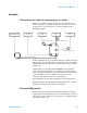
Both PCMs and auxiliary channels are controlled by pressure
setpoints. To work properly, there must be adequate flow
resistance downstream of the pressure sensor. Each channel
provides a frit- type restrictor. Four frits are available.
The brown ring frit is in all channels in the AUX epc when the
instrument is shipped. No frit ships in the PCM Aux channel.
When installing or replacing a frit, always use a new O- ring
(5180- 4181, 12/pk).
Selecting a frit
The frits change the control range of the channels. The objective
is to find a frit that allows the required range of flows at
reasonable source pressures.
• For an auxiliary channel ordered as an option (part of the
GC order), use the frit supplied by the factory.
• For an auxiliary channel ordered as an accessory (separate
from the GC order), see the instruction information supplied
with the accessory.
• For a non- Agilent instrument, you must experiment to find
the appropriate frit.
When you change a frit, you change the physical characteristics
of the channel. It may be desirable (or necessary) to change the
PID constants for that channel. See “PIDs” on page 155.
Table 24 Auxiliary channel frits
Frit marking Flow resistance Flow characteristic Often used with
Three blue rings High 3.33 ± 0.3 SCCM @ 15 PSIG FID Air, QuickSwap,
Splitter, Deans Switch
Two red rings Medium 30 ± 1.5 SCCM H2 @ 15 PSIG FID Hydrogen
One brown ring Low 400 ± 30 SCCM AIR @ 40 PSIG NPD Hydrogen
None (brass tube) Zero No restriction Headspace vial
pressurization