
User guide


Flow and Pressure Modules 7
Advanced User Guide 161
Auxiliary Pressure Controllers
The Auxiliary Pressure Controller (Aux epc) is also a general
purpose device. It has three independent forward- pressure
regulated channels. Channels are designated by numbers 1
through 9 (there can be up to 3 Aux epcs), depending on where
the module is installed.
If an auxiliary channel is specified as the Inlet during column
configuration, that channel allows run time programming and
three- ramp flow or pressure programming.
Gas input is via threaded fittings. Gas output is via coils of
metal tubing with Swagelok fittings on the ends.
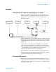
As you look at the module from the back of the GC, the channels
are numbered from left to right according to this scheme:
• In slot 6. The name is Aux epc #, where # is 1, 2, or 3 and
identifies the channel.
• In slot 5. The name is Aux epc #, where # is 4, 5, or 6 and
identifies the channel.
• In slot 4. The name is Aux epc #, where # is 7, 8, or 9 and
identifies the channel.
• In the third detector side of the GC. The name is Aux epc #,
where # is 7, 8, or 9 and identifies the channel.
Split vent trap
and valve
Slot 1
Slot 2
Slot 3
Back of GC
Aux epc 1, 2, 3
Aux epc 4, 5, 6
Aux epc 7, 8, 9