Agilent G3180B Two-Way Splitter Kit With Makeup Gas Installation and Operation Guide Agilent Technologies
Notices ©Agilent Technologies, Inc. 2006 Warranty No part of this manual may be reproduced in any form or by any means (including electronic storage and retrieval or translation into a foreign language) without prior agreement and written consent from Agilent Technologies, Inc. as governed by United States and international copyright laws. The material contained in this document is provided “as is,” and is subject to being changed, without notice, in future editions.
In this Guide. . . This Installation and Operation Guide contains information for installing and using an effluent splitter on an Agilent 6890 gas chromatograph (GC). The G3180 splitter is intended for use with capillary columns and uses makeup gas to maintain adequate flows throughout the system. 1 Introduction This chapter describes how the splitter works, the GC and software requirements of the system and the contents of the installation kit.
Installation and Operation Guide
Contents 1 Introduction Overview 8 How It Works 9 Details 10 Metal ferrules 10 Microfluidic plate 10 Constant pressure operation 10 Calculation of chromatographic parameters GC Requirements 12 Other Requirements Parts Supplied 14 Parts Not Supplied 2 12 13 Part Identification Tools Required 11 15 15 Hardware Installation Prepare the GC 18 Install the Column Clips 20 Install the Bracket and Splitter 21 Connect the Makeup Gas Supply 24 To supply the makeup gas froma PCM 24 To supply th
3 Splitter Configurations Typical Configurations 26 Splitting to an MSD 28 Custom Configurations 29 Restrictor id and length 32 Maximum and minimum flows Column outlet pressure 34 Inlet pressure 34 33 Restrictor and Column Installation 35 Install the column 35 Connect the splitter 35 Disconnect tubing from the splitter 37 4 Operation An Example 40 Column flow 40 Select restrictors 42 Calculate column flow 43 Calculate ECD restrictor flow Calculate MSD restrictor flow 44 45 Changing Columns Without Ven
Agilent G3180B Splitter Kit Installation and Operation Guide 1 Introduction Overview 8 How It Works 9 Details 10 Metal ferrules 10 Microfluidic plate 10 Constant pressure operation 10 Calculation of chromatographic parameters 11 GC Requirements 12 Other Requirements 12 Parts Supplied 13 Part Identification 14 Parts Not Supplied 15 Tools Required 15 This manual covers the installation and operation of the G3180B effluent splitter with makeup gas kit on the Agilent 6890 series gas chromatograph (GC).
1 Introduction Overview Splitter installation is done in three steps: 1 Hardware installation. This gets the hardware installed and the gas flows connected. 2 Restrictor configuration. You can choose to use a typical, precalculated configuration or create a custom one using software tools supplied on a CD. 3 Restrictor and column installation. Using the results of step 2, cut the appropriate lengths of the appropriate diameter tubing for the restrictors. Install the restrictors and the analytical column.
Introduction 1 How It Works The splitter divides the effluent from a column between two different detectors.
1 Introduction The column flow mixes with the makeup flow in the splitter. This mixture then flows through lengths of uncoated, deactivated, fused-silica tubing to each detector. These tubes act as flow restrictors. While the flow through each restrictor changes with oven temperature, the ratio of the two flows at any temperature is the same.
Introduction 1 Calculation of chromatographic parameters Because the pressure at the split point is known and constant, the chromatographic parameters can be calculated before setup. This is especially useful with GC/MSD setups, where there are limitations on the flow rates of carrier gas allowed into the MSD. If a method that was originally developed on an MSD is converted to a splitter setup, a new inlet pressure can be calculated to produce retention times very similar to the original method.
1 Introduction GC Requirements The splitter mounts in an Agilent 6890 series GC. The splitter requires an electronically controlled pressure source such as the Three Channel Pressure controller (6890 option 205, 301, or 308) or a Pneumatics Control Module (PCM). Other Requirements The calculator requires Microsof®t Excel 97 (or later), which is not supplied with this kit.
Introduction 1 Parts Supplied The G3180B kit contains the following parts (Table 1).
1 Introduction Part Identification Most of the kit parts are easily recognized. The unique ones are identified in Figure 2. Capillary column spring clips Valve box blanking plate Oven bracket assembly Compact splitter with makeup gas assembly Figure 2 14 This assembly is shipped in a plastic bag to keep contaminants out of the tubing and the fittings. Do not open the bag until you are ready to install the splitter.
Introduction 1 Parts Not Supplied Brown-dot frit (19231-60610) Tools Required Side cutter, large Open-end wrenches Installation and Operation Guide 15
1 16 Introduction Installation and Operation Guide
Agilent G3180B Splitter Kit Installation and Operation Guide 2 Hardware Installation Prepare the GC 18 Install the Column Clips 20 Install the Bracket and Splitter 21 Connect the Makeup Gas Supply 24 This chapter describes the procedure for installing the splitter hardware and connecting the makeup gas supply.
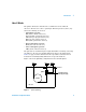
2 Hardware Installation Prepare the GC WA R N I N G Turn the power off and disconnect the power cord before proceeding. 1 Raise the GC top cover to expose the oven top. 2 Remove the valve box cutout using a side cutter (Figure 3).
2 Hardware Installation 3 This exposes a layer of soft insulation. Remove it to expose the hard oven insulation. Remove the precut insulation piece at the location shown in Figure 4. Remove this cutout Figure 4 Remove the insulation cutout 4 Replace the soft insulation. Install the valve box blanking plate, using one screw at the front and one at the rear to secure it. See Figure 5.
2 Hardware Installation Install the Column Clips Install the four column clips on the oven shroud (Figure 6).
Hardware Installation 2 Install the Bracket and Splitter The splitter is usually installed on the right side of the oven. NOTE The body of the splitter may be discolored as a result of the deactivation process. This is not a defect. 1 Place the bracket against the side of the oven. The two notches should be up and the standoffs should face the center of the oven. 2 Use two T-shaped thumbscrews to fasten the bracket to the T-slots in the oven wall (Figure 7).
2 Hardware Installation CAUTION Use extreme care to prevent any fragments of insulation or other material from entering the makeup gas tubing or the fittings on the splitter assembly. Such materials could block the internal passages in the splitter or the bore of the capillary restrictors. CAUTION In the following steps, bend the tubing over an object such as your thumb to avoid kinks. 3 Open the plastic bag and remove the splitter assembly. Install a plastic cap on the end of the makeup gas tubing.
2 Hardware Installation 6 Route the prebent tubing against the oven wall and top to keep it clean for future maintenance. It should be behind the back detector location. 7 Screw the splitter assembly to the bracket (three screws). See Figure 9.
2 Hardware Installation Connect the Makeup Gas Supply Connect the makeup gas source to the PCM or Auxiliary Pressure controller. To supply the makeup gas froma PCM 1 Connect the tubing from the PCM to the 1 meter length of stainless steel tubing from the kit with a union. 2 Connect the free end of the stainless steel tubing to the tubing from the splitter assembly with a union. See Figure 10.
Agilent G3180B Splitter Kit Installation and Operation Guide 3 Splitter Configurations Typical Configurations 26 Splitting to an MSD 28 Custom Configurations 29 Restrictor id and length 32 Maximum and minimum flows 33 Column outlet pressure 34 Inlet pressure 34 Restrictor and Column Installation 35 Install the column 35 Connect the splitter 35 Disconnect tubing from the splitter 37 The combination of restrictor diameters and lengths determines how the column effluent is divided (the split ratio) between t
3 Splitter Configurations Typical Configurations The important parameters when setting up a splitter are the lengths and diameters of the restrictor tubes that go to the two detectors. The dimensions of the restrictors are chosen to give the desired split ratio, flow to the detector, and to minimize peak broadening.
Splitter Configurations Table 3 3 Splitter flows 40 °C 200 °C 300 °C 400 °C Configuration Flow R1, mL/min Flow R2, mL/min Flow R1, mL/min Flow R2, mL/min Flow R1, mL/min Flow R2, mL/min Flow R1, mL/min Flow R2, mL/min 1 14.7 14.7 7.3 7.3 5.2 5.2 3.9 3.9 2 5.1 25.6 2.5 12.7 1.8 9.1 1.4 6.8 3 2 2 1 1 0.7 0.7 0.54 0.54 4 4 4 2 2 1.4 1.4 1.1 1.1 5 1 2 0.5 1 0.36 0.72 0.27 0.54 6 2 4 1 2 0.71 1.4 0.53 1.06 7 0.4 2 0.2 1 0.14 0.7 0.1 0.
3 Splitter Configurations For constant pressure methods, first find the maximum flow as above. Use the GC, ChemStation, Flow Calculator Software or the Method Translation Software to find the inlet pressure that gives the maximum flow at the upper temperature of the method (make sure the column outlet pressure is set to 3.8 psig for the calculation). For example, if a 30 m × 0.32-mm id column is used with Configuration 1, using helium carrier and programming to 300 °C, the pressure that gives a flow of 9.
3 Splitter Configurations Custom Configurations The CD supplied with this kit contains three software tools: Effluent Splitter Calculator (with Makeup) Calculates dimensions (length and inside diameter) of restrictors to obtain a desired split ratio (Figure 11).
3 Splitter Configurations GC Method Translation Converts an analytical method from one set of operating conditions to another (Figure 12).
3 Splitter Configurations Column Pressure/Flow Calculator Calculates flows and pressures for a given set of column (or restrictor) dimensions (Figure 13). Figure 13 Column Flow/Pressure Calculator These tools allow you to perform all the calculations needed to create a custom splitter configuration. We recommend that you load the CD software into your PC. 1 Insert the CD into the drive and click the Start icon in the bottom left of the screen.
3 Splitter Configurations Restrictor id and length 1 Run the Effluent Splitter Calculator and enter the following information. The calculator provides a list of possible restrictors. • Column flow. Use the ChemStation, GC, Flow Calculator, or Method Translation Software to determine the column flow in mL/min (with the column outlet at 3.8 psig) at the initial oven temperature. • Initial oven temperature.
Splitter Configurations 3 Maximum and minimum flows The maximum suggested flow for MSDs depends on the vacuum pump used. For diffusion pump and standard turbo systems, the flow should not exceed 2 mL/min. For performance turbo systems, the flow should not exceed 4 mL/min. These flow limits restrict the column flows and split ratios that can be used with MSDs. Make sure that the flow through each restrictor tube is at least equal to the suggested minimum flow in Table 4.
3 Splitter Configurations Column outlet pressure The 6890 GC needs to know the pressure at the end of the column to be able to calculate column flows. Use either the GC keyboard or the ChemStation to set the outlet pressure for the column to 3.8 psig. The ChemStation screen where the column outlet pressure is set is shown in Figure 14.
3 Splitter Configurations Restrictor and Column Installation NOTE Restrictors and the column exit are connected to the splitter assembly using internal nuts and SilTite ferrules. See “Swaging SilTite Ferrules” on the CD for details. Install the column 1 Hang the analytical column on the column clips. The clips hold the outside of the wire “basket” that supports the column. Adjust the clips if necessary. 2 Connect the column to the inlet fitting.
3 Splitter Configurations To makeup gas supply Restrictor 2 to Detector 2 Restrictor 1 to Detector 1 Column exit Figure 15 CAUTION 36 Restrictor and column connections Do not overtighten the fittings. The dashed line in Figure 16 (about 15° clockwise from finger-tight) is usually enough.
Splitter Configurations 3 15° Figure 16 Tightening the connections Disconnect tubing from the splitter Loosen and remove the internal nut from the splitter fitting. Usually the tubing and ferrule will fall out of the fitting. Occasionally the ferrule will stick in the fitting. If this happens, use a pointed object like a pen or a paper clip and insert it in the ferrule release hole in the side of the fitting (Figure 17). Press firmly. The ferrule will click when it breaks free.
3 Splitter Configurations Protect the column and restrictors Column and restrictor tubes with swaged metal ferrules can be disconnected and reconnected several times. To protect the tubing end, use one of the brass-sealing caps from the kit. Tighten to finger-tight plus 15 degrees. Protect the splitter Seal the ports of the splitter assembly with plugs when the splitter is not connected. This keeps particulates and contamination out.
Agilent G3180B Splitter Kit Installation and Operation Guide 4 Operation An Example 40 Column flow 40 Select restrictors 42 Calculate column flow 43 Calculate ECD restrictor flow 44 Calculate MSD restrictor flow 45 Changing Columns Without Venting the MSD 46 Backflushing the Column 47 This chapter contains a worked-through custom configuration, plus some special topics.
4 Operation An Example Assume we have a method that uses an HP-5MS column (30 m × 250 µm id × 0.25-µm film thickness) to measure pesticides with an MSD. The initial oven temperature is 70 °C and is programmed to 280 οC. The method is run in constant pressure mode at 19.44 psig inlet pressure and the carrier gas is helium. The initial column flow listed by the ChemStation is 2.1 mL/min.
Operation Figure 18 4 Calculating column flow The outlet pressure entered for the new splitter method must be in absolute pressure units. Since the outlet of the column will be 3.8 psig, we need to convert this to psia for the method translator. Absolute pressure = gauge pressure + 14.696. Hence, 3.8 + 14.696 = 18.496 will be entered. The calculated inlet pressure for the new splitter method is 30.93 psig and the new column flow is 3.09 mL/min.
4 Operation Select restrictors Start up the spreadsheet "splitter_calc.xls" in Excel. We will choose to have 2 mL/min go to the ECD initially. With a split ratio of 3, this will send 6 mL/min to the MSD. This flow is acceptable with a performance turbo system but will give somewhat degraded detection limits. Fill in the input column as shown (Figure 19) with the ECD assumed to be Detector 1 and the MSD as Detector 2.
Operation 4 The calculator lists the lengths required for the different sizes of uncoated, deactivated, fused-silica, restrictor tubing available. Choose the id tubing that gives the shortest length of at least 0.3 m for most detectors and 0.8 m for MSDs. In this case 0.18-mm id is the choice, requiring 0.912 m for the ECD restrictor and 0.824 m for the MSD restrictor. Table 4 on page 33 shows that in both cases the flow is higher than the minimum 0.72 mL/min suggested for helium in 0.18-mm id tubing.
4 Operation Calculate ECD restrictor flow The flow through the ECD restrictor at 280 °C is calculated to be 0.88 mL/min (Figure 21). Figure 21 ECD restrictor flow calculation This flow is higher than the minimum 0.72 mL/min suggested for helium in 0.18-mm id tubing.
Operation 4 Calculate MSD restrictor flow The flow through the MSD restrictor (Figure 22) at 280 °C is: Figure 22 MSD restrictor flow calculation The flow to the MSD at 280 °C is 2.65 mL/min. This flow is higher than the minimum 0.72 mL/min suggested for helium in 0.18-mm id tubing. The calculated makeup flow is then [0.88 + 2.65] – 1.38 = 2.15 mL/min. This should work well. The configuration can now be installed and used.
4 Operation Changing Columns Without Venting the MSD For systems that use an MSD attached to the splitter, one added advantage is the GC column can be changed without venting the MSD. When the column is disconnected from the splitter plate, the makeup gas purges air out of the fitting, preventing air from reaching the MSD. To change columns with the splitter, the recommended steps are: 1 Cool down the inlet to which the column to be removed is connected. 2 Disconnect the column from the splitter plate.
Operation 4 Backflushing the Column One useful feature available with EPC control of the makeup is the ability to backflush unwanted higher boiling analytes from the column. Use of this feature requires that the split/splitless inlet be used. Backflushing reduces the hold at the end of the run to clean out the column. To backflush, the splitter makeup pressure is time-programmed to rise rapidly after elution of the last peak of interest while the inlet pressure decreases rapidly.
4 Operation The restrictor to the MSD was 0.824 m of 0.18-mm id tubing. The backflushing temperature used here is the hold temperature at the end of the run in the original method (280 °C). The flow calculator (Figure 23) shows that the makeup pressure can be programmed to 17.4 psig at 280 °C. Figure 23 Column backflush flow calculation The time required for complete backflushing of heavy materials is then determined empirically.
Index A Excel, 12 Absolute pressure, 41 Aux EPC, 27 Auxiliary Pressure controller, 24 F B Backflushing, 47 C Changing columns, 46 Column connections, 35 flow, 10, 26, 27, 43 outlet pressure, 34 Column clips, 35 Column effluent, 27 Configuration, 9 custom, 25, 29 typical, 25, 26 Constant flow mode, 27 Constant pressure mode, 28 Constant pressure operation, 10 Custom configuration, 29 Example, 40 D Detector Above atmospheric pressure, 9 Atmospheric pressure, 9 Below atmospheric pressure, 9 flow rate, 26
Installation and Operation Guide 50
Agilent Technologies © Agilent Technologies, Inc.