
Technical data


Table Of Contents
- Content
- Installation
- Set-Up
- Installation Verification
- Step 1. Auto tune
- Step 2. Set up method names and parameters
- Step 3. Create MMCHECKTOF_EI_POS.m
- Step 4. Create MMCHECKTOF_EI_NEG.m
- Step 5. Create MMCHECKTOF_CI_POS.m
- Step 6. Create MMCHECKTOF_CI_NEG.m
- Step 7. Create MMCHECKTOF_MX_EI POS_CI POS.m
- Step 8. Create MMCHECKTOF_MX_EI NEG_CI NEG.m
- Step 9. Run each of the methods created
- Step 10. Calculate the response of Multimode Demo
- Step 11. Fill out Multimode Report for calculation of peak heights
- Index
Multimode Source for 6510 Q-TOF LC/MS Set-Up Guide 9
Installation 1
Step 2. Install the HV control PCA and cables
Step 2. Install the HV control PCA and cables
1 Turn off the system power and remove the system power cord.
The power cord should be kept intact if the vacuum control switch box is
used. The switch box is intended to keep the vacuum on while a service
engineer works on the electronics. The switch box is for service engineer
use only.
2 Remove the CDS cover, top, side, front, and the Aux Module cover.
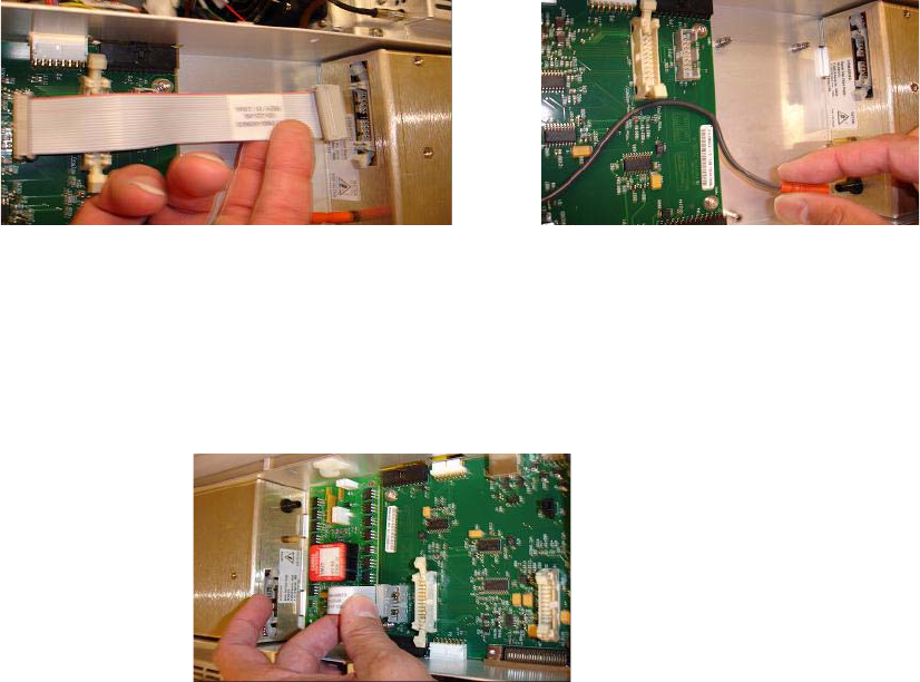
3 Disconnect the ribbon cable that connects the valve PCA to the
Vcap/Vchamber power supply. Then disconnect the Vcap and Vchamber
cable from the power supply.
Figure 3 Disconnecting the Vcap/Vchamber power supply from the valve PCA (left) and the Vcap/Vchamber.
4 Place the multimode HV power supply PCA in the slot between the valve
PCA and the Vcap/Vchamber power supply. Secure the board by pressing it
down into its slot and then attach it with two screws.
5 Connect the short gray cable from the valve PCA to the multimode HV
power supply.
Figure 4 Connecting the valve PCA to the multimode HV power supply.