
Technical data


Table Of Contents
- Content
- Installation
- Set-Up
- Installation Verification
- Step 1. Auto tune
- Step 2. Set up method names and parameters
- Step 3. Create MMCHECKTOF_EI_POS.m
- Step 4. Create MMCHECKTOF_EI_NEG.m
- Step 5. Create MMCHECKTOF_CI_POS.m
- Step 6. Create MMCHECKTOF_CI_NEG.m
- Step 7. Create MMCHECKTOF_MX_EI POS_CI POS.m
- Step 8. Create MMCHECKTOF_MX_EI NEG_CI NEG.m
- Step 9. Run each of the methods created
- Step 10. Calculate the response of Multimode Demo
- Step 11. Fill out Multimode Report for calculation of peak heights
- Index
8 Multimode Source for 6510 Q-TOF LC/MS Set-Up Guide
1 Installation
Step 1. Prepare to install
Step 1. Prepare to install
The Multimode Enablement Kit, G1978-60451, is shipped with the multimode
source. This kit needs to be installed before the multimode source is used.
Note that the multimode source and its accessories are to be installed by an
Agilent Customer Engineer.
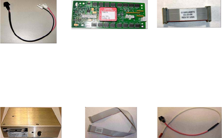
1 Check that the Multimode Enablement Kit contains the following parts:
• Multimode Bd HV Cable, p/n G1960-60858
• Multimode HV PCA, p/n G1960-61015
• Multimode Bd Power/Data Cable, p/n G1960-60873
Figure 1 From left to right: G1960-60858, G1960-61015 and G1960-60873
2 Install the APCI Enablement Kit, G1947-60451, which is shipped with the
multimode source.
The APCI Enablement kit contains the following parts:
• Fast APCI HV Supply, p/n G1946-80058
• Valve BD-APCI Supply Cable, p/nG1960-60802
• Valve BD-APCI Needle Interlock Cable, p/n G1960-60856
Figure 2 From left to right: G1946-80058, G1960-60802 and G1960-60856