
Technical data


Table Of Contents
- Content
- Installation
- Set-Up
- Installation Verification
- Step 1. Auto tune
- Step 2. Set up method names and parameters
- Step 3. Create MMCHECKTOF_EI_POS.m
- Step 4. Create MMCHECKTOF_EI_NEG.m
- Step 5. Create MMCHECKTOF_CI_POS.m
- Step 6. Create MMCHECKTOF_CI_NEG.m
- Step 7. Create MMCHECKTOF_MX_EI POS_CI POS.m
- Step 8. Create MMCHECKTOF_MX_EI NEG_CI NEG.m
- Step 9. Run each of the methods created
- Step 10. Calculate the response of Multimode Demo
- Step 11. Fill out Multimode Report for calculation of peak heights
- Index
Multimode Source for 6510 Q-TOF LC/MS Set-Up Guide 17
Installation 1
To convert from ESI or APCI to the multimode source
Figure 13 Multimode spray shield
11 Screw the multimode spray shield into the holder for the spray shield. See
Figure 14.
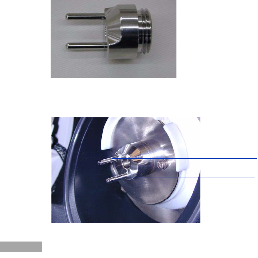
Figure 14 Multimode spray shield installed
12 Remove the shipping cover from the multimode source spray chamber.
Field shaping electrode
9 o'clock position
Field shaping electrode
6 o'clock position
NOTE
The field shaping electrodes should be in the nine o’clock and the six o’clock position.
Loosen the end plate screws on each side to adjust the field shaping electrodes position.