
Technical data


Table Of Contents
- Content
- Installation
- Set-Up
- Installation Verification
- Step 1. Auto tune
- Step 2. Set up method names and parameters
- Step 3. Create MMCHECKTOF_EI_POS.m
- Step 4. Create MMCHECKTOF_EI_NEG.m
- Step 5. Create MMCHECKTOF_CI_POS.m
- Step 6. Create MMCHECKTOF_CI_NEG.m
- Step 7. Create MMCHECKTOF_MX_EI POS_CI POS.m
- Step 8. Create MMCHECKTOF_MX_EI NEG_CI NEG.m
- Step 9. Run each of the methods created
- Step 10. Calculate the response of Multimode Demo
- Step 11. Fill out Multimode Report for calculation of peak heights
- Index
Multimode Source for 6510 Q-TOF LC/MS Set-Up Guide 11
Installation 1
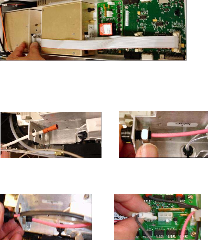
Step 2. Install the HV control PCA and cables
Figure 7 Connecting the APCI HV power supply to the valve PCA.
10 Insert one end of the APCI Needle Interlock cable, G1960-60856, through
the slot at the front of the system and then plug it to the APCI HV
connector. Attach the other end to the chassis with the o-ring and the nut
(see Figure 8).
Figure 8 Connecting the APCI HV to the chassis.
11 Insert the cable, G1960-60858, to the top slot and attach it to the chassis.
Plug the other two ends into the multimode HV PCA.
Figure 9 Connecting the HV PCA to the chassis.
12 Close the AUX Module cover and reconnect all cables.
13 Install the multimode source onto the system and connect all connectors.