
Technical data


Table Of Contents
- Content
- Installation
- Set-Up
- Installation Verification
- Step 1. Auto tune
- Step 2. Set up method names and parameters
- Step 3. Create MMCHECKTOF_EI_POS.m
- Step 4. Create MMCHECKTOF_EI_NEG.m
- Step 5. Create MMCHECKTOF_CI_POS.m
- Step 6. Create MMCHECKTOF_CI_NEG.m
- Step 7. Create MMCHECKTOF_MX_EI POS_CI POS.m
- Step 8. Create MMCHECKTOF_MX_EI NEG_CI NEG.m
- Step 9. Run each of the methods created
- Step 10. Calculate the response of Multimode Demo
- Step 11. Fill out Multimode Report for calculation of peak heights
- Index
10 Multimode Source for 6510 Q-TOF LC/MS Set-Up Guide
1 Installation
Step 2. Install the HV control PCA and cables
6 Install the APCI HV power supply. The APCI HV power supply is located at
the end of the AUX Module.
7 Connect ribbon cable between the valve PCA and Vcap/Vchamber power
supply.
Figure 5 Connecting the valve PCA to the Vcap/Vchamber power supply.
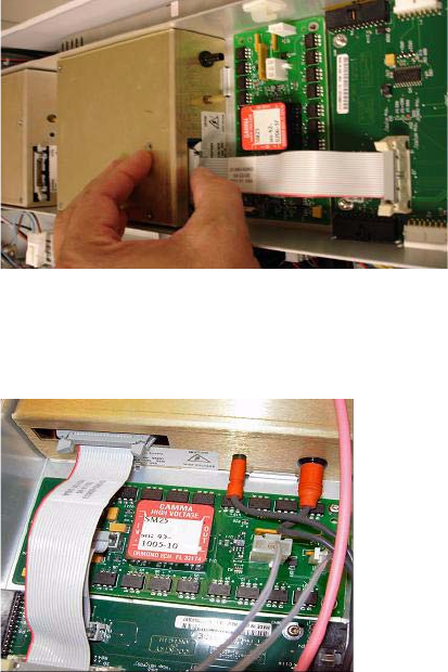
8 Connect the Vcap and Vchamber cables to the Vcap/Vchamber power
supply.
Figure 6 Connecting the Vcap and Vchamber cables to the power supply.
9 Connect the long ribbon cable, p/n G1960-60802, from the APCI HV power
supply to the valve PCA.