
Specifications


$JLOHQW0$996HULHV6HUYLFH*XLGH
5HSDLULQJWKH$JLOHQW0RGHO9
Repairing the Agilent
Model V24
5HPRYLQJWKH6\VWHP%RDUG
Remove the Front Housing Assembly.
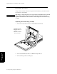
Disconnect the cables from the System Board as shown below.
Using a small (1/8” inch) flat-blade screwdriver, pry the service port cover from the Rear
Housing and remove.
6\VWHP%RDUGLQWHUIDFH
FRQQHFWRUV
1. Keypad connector
2. Flat Panel Data Connector
3. 5V and 12V power
supply connector
4. Service ports (not cabled)
5. SDN interface cable
6. Defib sync connector
(not cabled)
7. Front-end link connector
8. Speaker connector
9. 60 VDC power supply
connector
10. RS232 connector (with option
J13)
6
7
5
2
4
1
3
8
Service Port Cover
9
10