
User`s guide

344 Agilent X-Series Signal Generators User’s Guide
Custom Digital Modulation (Option 431)
Using the Arbitrary Waveform Generator
Defining a Modulation
You can build a unique modulation by utilizing two tools, the FSK table editor or the I/Q table editor.
These tables map data onto specific absolute modulation states. To map transitions between states, a
differential table editor is provided.
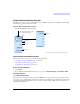
Building an Asymmetric FSK Modulation with the FSK Table Editor
You can use the FSK table editor to create customized asymmetric FSK modulation of up to 16 levels,
then apply the custom FSK modulation to one of the modulation standards. An example of this
capability is to create an interfering signal for adjacent channel selectivity testing of FLEX
ΤΜ
pagers.
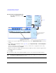
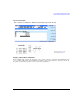
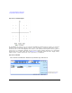
To do this, build a 4- level FSK modulation at 4.8 kHz and 1.6 kHz in the FSK table editor, shown in
Figure 13- 22. Then use this signal to modulate a PN15 data transmission. In the FLEX
ΤΜ
protocol,
each of the levels in 4- level FSK represents a 2- bit sequence.
Create a Continuous 4-Level FSK Signal
Use this procedure to create a 4- level FSK signal for adjacent channel testing of FLEX
ΤΜ
pagers.
1. Press Preset on the signal generator.
2. Press Mode > Real-Time Custom Modulation > Modulation Setup > Modulation Type > Define User FSK.
3. Enter the frequency deviations shown in Figure 13- 22 into the FSK table editor.
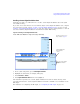
4. Store the file as 4FSK. Press Load/Store > Store To File > 4FSK > Enter.
5. Load the file. Press Load from Selected File > Confirm Load From File.
6. Turn on Custom Modulation. Press Return > Return > Return > Real-Time Custom On.
7. Set the Frequency to the desired carrier frequency for the adjacent channel.
8. Set the desired Amplitude.
9. Press RF On. The amplitude of the interferer can then be adjusted to measure the performance of
the device under test.