
User`s guide

14 Agilent X-Series Signal Generators User’s Guide
Signal Generator Overview
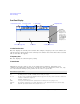
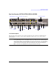
Rear Panel Overview (N5171B, N5172B, N5181B, & N5182B)
2. EXT 1 & EXT 2
3. LF OUT
4. SWEEP OUT
5. PULSE
6. TRIG 1 & 2
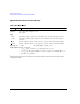
7. REF IN
In its factory default mode, the signal generator can detect a valid reference signal at this connector
and automatically switch from internal to external reference operation. See “Presetting the Signal
Generator” on page 44. With Option 1ER (flexible reference input), you must explicitly tell the signal
generator the external reference frequency you wish to use; enter the information through the front
Connector female BNC Impedance nominally 50 Ω
Signal An externally supplied ±1 V
p
signal that produces the indicated depth.
Damage Levels 5 V
rms
and 10 V
p
Connector female BNC Impedance 50 Ω
Signal Voltage range: 0 to +5 V
p
Offset: - 5 V to +5 V, nominal
For more information, see page 81.
Connector female BNC
Can drive 2 kΩ.
Impedance <1 Ω
Signal Voltage range: 0 to +10 V, regardless of sweep width
In swept mode: beginning of sweep = 0 V; end of sweep = +10 V
In CW mode: no output
This is a multiple use connector. For signal routing selections, see pages 52 and 129.
Connector female BNC Impedance nominally 50 Ω
Signal
Externally supplied: +1 V = on; 0 V = off
Damage Levels ≤ −0.3 and ≥+5.3 V
Connector female BNC Impedance high Z
Signal An externally supplied TTL or CMOS signal for triggering operations, such as point to point
in manual sweep mode or an LF sweep in external sweep mode.
Triggering can occur on either the positive or negative edge.
Damage Levels ≤ −0.5 and ≥+5.5 V
Connector female BNC Impedance nominally 50 Ω
Signal An externally supplied −3.5 to +20 dBm signal from a timebase reference that is within ±1 ppm.