
Specifications

1-52 Programming Guide
Preparing for Use ESG Family Signal Generators
Programming the Status Register System
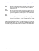
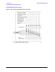
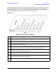
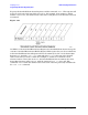
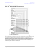
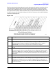
Figure 1-24.
Bit Description
0 A 1 in this bit position indicates that an I/Q calibration is being performed.
1, 2 Unused. These bits are always set to 0.
3 A 1 in this bit position indicates that a sweep is in progress.
4 A 1 in this bit position indicates that a bit error rate test is in progress
(Options UN7 and 300 only).
5 A 1 in this bit position indicates that the source is in a “wait for trigger” state of the
trigger model.
6, 7, 8 Unused. These bits are always set to 0.
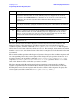
9 A 1 in this bit position indicates that the signal generator is currently performing a
DCFM/DC
ΦM zero calibration.
10 A 1 in this bit position indicates that the signal generator is currently busy
processing ARB commands.
11 A 1 in this bit position indicates that the signal generator is currently doing the
necessary pre-sweep calculations.
12 A 1 in this bit position indicates that the signal generator is currently
synchronizing to BCH. TCH, and PRBS.
13, 14 Unused. These bits are always set to zero.
15 Always Zero (0).