
User`s guide
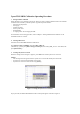
5-2) Define each standard as follows:
Reference impedance Z0
Enter the reference impedance value for the through, match and line standards.
Reflection
Select the standard type you use (short or open) and enter its delay value.
Thru
Enter the delay value of the through standard. If necessary, also enter its offset loss value.
Match
Enter the frequency range of the match standard.
Line
You can define up to three lines: Line 1, Line 2, and Line 3. For each line standard, enter the delay value
and the frequency range.
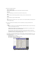
5-3) Activate the match and line standards you use for the calibration by entering check marks in the
checkboxes.
NOTES
- Reference impedance Z0 of the TRL/LRM Calibration VBA Macro must be set to the same value as
the ENA’s system impedance Z0 value.
- Calibration reference plane is set to the middle of the through standard. It is not possible to set the
calibration reference plane with the reflection standard.
- When the frequency ranges of the line and the match overlap, the data of the line is used in the
overlapped frequency area. When the frequency ranges of multiple lines overlap, the data of the line
measured later is used in the overlapped frequency areas.
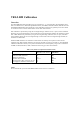
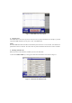
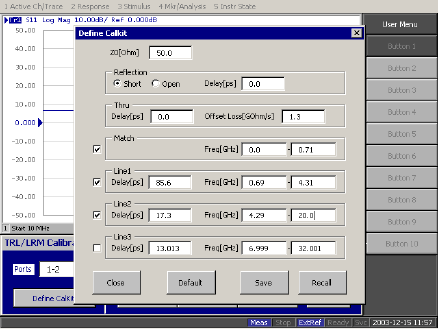
For example, if you define the calibration kits as shown in Figure 4 and perform the Match, Line 1, and
Line 2 measurements in this order, the analyzer uses the following three different calibrations depending
on the frequency ranges:
- TRM calibration: below 690 MHz
- TRL calibration with Line 1: 690 MHz to 4.29 GHz
- TRL calibration with Line 2: over 4.29 GHz
Figure 4. Calibration kit definition example
Figure 4. Calibration kit definition exampleFigure 4. Calibration kit definition example
Figure 4. Calibration kit definition example