Agilent E5070B/E5071B ENA Series RF Network Analyzers TRL/LRM Calibration First Edition No.
Notices The information contained in this document is subject to change without notice. This document contains proprietary information that is protected by copyright. All rightsare reserved. No part of this document may be photocopied, reproduced, or translated toanother language without the prior written consent of Agilent Technologies. Agilent Technologies Japan, Ltd.
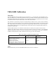
TRL/LRM Calibration Overview The TRL/LRM Calibration VBA Macro lets you perform the 2-, 3-, and 4-port TRL (Through-Reflect-Line), LRL (Line-Reflect-Line), TRM (Through-Reflect-Match), and LRM (Line-Reflect-Match) calibrations for the E5070B/E5071B ENA RF network analyzers. These calibration techniques are generally used in non-coaxial environments such as in-fixture measurements and on-wafer measurements.
To perform TRL/LRM calibration, you need to prepare calibration standards that meet the following requirements: Through (zero-length, or non-zero-length through) Zero-length through - S21 and S12 are defined as equal to 1. - S11 and S22 are defined as equal to zero. Non-zero-length through - Z0 of the through and lines must be the same. - Attenuation need not be known. - Accurate electrical length must be known to set the reference plane.
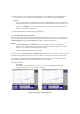
Installation of TRL/LRM Calibration VBA Macro NOTE Before installing this VBA macro, make sure that your E5070B/E5071B’s firmware revision is 3.5 or above. Installation Procedure 1) Prepare the floppy disk that contains the installation program, “E507X_TRL_LRM_CAL_100.msi”. 2) Reboot the ENA (Turn the ENA’s power OFF, and then turn it ON again). 3) Insert the floppy disk in the ENA. 4) Press [Save/Recall], Explorer to open the Windows Explorer and double-click on the installation program in the A drive.
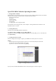
2-port TRL/LRM Calibration Operating Procedure 1. Setting stimulus conditions Select the ENA’s active channel to the one for which you want to perform calibration and set the stimulus conditions of the channel by manual operation.
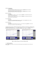
Figure 2. TRL/LRM main control panel 4. Selecting ports In the Ports menu, select the test ports for which you want to perform calibration. For example, to perform 2-port TRL/LRM calibration for test ports 1 and 2, select Ports:1-2. NOTE The TRL/LRM Calibration VBA Macro automatically detects the ENA’s active channel, and calibration is performed for the active channel. The macro does not perform calibration for the ENA’s inactive channels. 5.
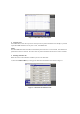
5-2) Define each standard as follows: Reference impedance Z0 Enter the reference impedance value for the through, match and line standards. Reflection Select the standard type you use (short or open) and enter its delay value. Thru Enter the delay value of the through standard. If necessary, also enter its offset loss value. Match Enter the frequency range of the match standard. Line You can define up to three lines: Line 1, Line 2, and Line 3.
5-4) If you want to save the current calibration kit definition, press the Save key and save the definition to your desired file. Saved calibration kit definition files can be recalled by pressing the Recall key. NOTES - If you save the calibration kit definition as “D:/Agilent/Trldata/Default.dat,” the file is handled as the default definition file. The default definition file is automatically recalled when the macro starts.
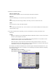
Reflection measurement: - Press Reflection. - Connect the Reflection standard to test port 1, and press [ ]Reflection 1. The reflection measurement is performed, and an asterisk appears. - Connect the Reflection standard to test port 2, and press [ ]Reflection 2. The reflection measurement is performed, and an asterisk appears. Match measurement: - Press Match. - Connect the Match standard to test port 1 and press [ ]Match 1. The Match measurement is performed, and an asterisk appears.
Multiport TRL/LRM Calibration Operating Procedure You can make 3- and 4-port TRL/LRM calibration in the same manner as 2-port TRL/LRM calibration. 1. Setting stimulus conditions Select the ENA’s active channel to the one for which you want to perform calibration and set the stimulus conditions of the channel by manual operation.
5. Defining calibration kit Define the values of the calibration standards in the same manner as 2-port TRL/LRM calibration. 6. Performing calibration measurement 6-1) Press each of the Thru, Reflection, and activated Match/Lines keys in the main control panel, and then press each calibration measurement key that appears in the User Menu area to perform the calibration measurements.
Reflection measurement: - Press Reflection. - Connect the Reflection standard to test port 1, and press [ ]Reflection 1. The reflection measurement is performed, and an asterisk is indicated. - Connect the Reflection standard to test port 2, and press [ ]Reflection 2. The reflection measurement is performed, and an asterisk is indicated. - Connect the Reflection standard to the test port 3, and press [ ]Reflection 3. The reflection measurement is performed, and an asterisk is indicated.