
User`s guide


Agilent EasyEXPERT User’s Guide Vol. 1, Edition 1 1- 83
Main GUI
Standby Channel Definition
Standby Channel Definition
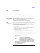
The Standby Channel Definition window is opened by clicking the Standby button,
and is used to define the standby channels and set the standby mode. See
“Standby
Function” on page 4-38.
The standby channel is the channel for maintaining specified output when the
standby mode is ON and in the non-measurement state. The standby channels will
be in the standby state, while the other channels will be in the idle state which is 0 V
output and 100 A compliance. When the standby mode is OFF and in the
non-measurement state, all channels will be in the idle state.
Standby Channel
Control
This area provides the following button.
Standby ON/OFF Sets the standby mode ON or OFF.
Standby Channel
Definition
This area defines the standby channels. The standby channels will start to output in
order, from the top to bottom, as listed in this area. The order of bias stop is bottom
to top.
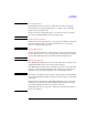
Standby Check the check box to specify the standby channel.
The radio button is used to select the channel setup available for
the Up/Down button.
Unit SMU or UHVU used for the standby output. To specify the
measurement resource connected to the selector (N1258A,
N1259A-300, N1265A) or N1266A expander, the channel must
be set to the Default output in the Configuration window.
Standby channel cannot be set for the SMU connected to the
ASU which makes the path to the AUX port.
Mode Output mode, V (voltage) or I (current)
Source Standby channel output value, in V or A
Compliance Compliance value, in A or V. Enter the current limit value for
the voltage source, or the voltage limit value for the current
source.
Up Moves the selected channel setup upward. To select a channel
setup, use the radio button on the left.
Down Moves the selected channel setup downward.