
User`s guide


Agilent EasyEXPERT User’s Guide Vol. 1, Edition 1 4- 39
Function Details
Standby Function
Output Sequence of Standby Channels
The standby channels will start to output in order, from the top to bottom, as listed in
the Standby Channel Definition on the Standby Channel Definition window. The
order of bias stop is bottom to top.
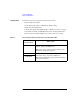
Figure 4-20 shows the standby and measurement operations for the following
example setup. This example assumes that the channel setup is defined in the
Standby Channel Definition as follows in the order show, and that the output value
in the standby state is the same as the output value in the measurement state.
• SMU1: Voltage source, non-standby channel
• SMU2: Voltage source, standby channel
• SMU3: Voltage source, standby channel
Figure 4-20 Standby Function
SMU1
SMU2
SMU3
Standby ON
Standby OFF
force V
force V
force V
V2
Measurement state
Standby state Standby state
Idle state Idle state
Idle state Idle state
V3
V1