
User`s guide


4- 38 Agilent EasyEXPERT User’s Guide Vol. 1, Edition 1
Function Details
Standby Function
Standby Function
This function forces the specified DC bias outputs (standby outputs) before starting
or after stopping a measurement.
Standby Channels
Standby channels are SMU or UHVU that force the standby output. Standby
channels maintain the specified DC bias output when the standby mode is ON and in
the non-measurement state.
Standby channel cannot be set for CMU, GNDU, and SMU connected to the atto
sense and switch unit (ASU) which makes the path to the AUX port.
To specify the measurement resource connected to the selector (N1258A,
N1259A-300, N1265A) or N1266A expander, the channel must be set to the Default
output in the Configuration window.
See “Standby Channel Definition” on page 1-83 to define the standby channels and
set the standby mode.
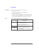
Standby State
Standby state is the state before starting or after stopping a measurement, in which
only the standby channels perform DC bias outputs. The other channels will be in
the idle state, which is 0 V output, 100 A compliance, SMU filter OFF, and series
resistor OFF. When the standby mode is OFF and in the non-measurement state, all
channels will be in the idle state.
When the B1500 is in the standby state, the measurement trigger stops the standby
state, so the standby channels stop the standby output and the measurement channels
perform a measurement (measurement state). After the measurement, the standby
channels start the standby output (standby state). During this series of operations,
the state is never changed to the idle state. See
Figure 4-20 for an example
operation.
If the bias hold function is enabled for the standby channel, after the measurement,
the channel forces the bias output set by the bias hold function. After the bias hold
period, the channel starts the standby output. During this series of operations, the
state is never changed to the idle state.