
User`s guide


Agilent EasyEXPERT User’s Guide Vol. 1, Edition 1 4- 35
Function Details
SPGU Module
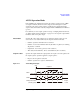
ALWG Operation Mode
In the ALWG mode (arbitrary linear waveform generator operation mode), SPGU
can output an arbitrary linear waveform voltage as shown in
Figure 4-19. The
waveform is the voltage pattern sequence specified by the pattern data and the
sequence data, which can be created by using the
Define ALWG Waveform Window
(p. 2-68).
For a summary of source output operation in sweep or sampling measurement mode,
see
“Pulse Output Operation Summary” on page 4-31. One sequence output will be
handled as same as one pulse output.
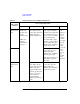
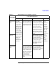
Pattern data Specifies all of the voltage patterns set to a channel. A pattern consists of some
vector data. A vector data is defined by the output level and the time data.
• Number of patterns: maximum 512 for a channel
• Number of vector data: maximum 1024-N (N: number of patterns) for defining
all patterns to a channel
• Output level: 0 to ± 40 V (open load, 1 mV resolution)
• Time data (incremental time): 10 ns to 671.088630 ms (10 ns resolution)
Sequence data Specifies the output channel, the output pattern, the repeat count of the pattern, and
the output sequence of patterns applied in a single sequence.
• Repeat count of a pattern: 1,048,576
• Number of patterns in a sequence: maximum 512
Figure 4-19 ALWG Output Example
SPGU1
SPGU2
Start
Pattern2
Pattern2
Pattern1
Pattern1
Pattern2
Pattern2
Pattern1
Pattern1
initial value
initial value
initial value
initial value
1 sequence
Pattern1
setup change (50 ns)
SPGU2 pulse switch
(normally open)
0: Open
1: Close
0
1
1
1
1
1
1
0
0
1
1
1
1
1
1
1
1
1
0
1
1
1
1
1
1
1
1
0
1
1
1
1
1
1
1
1
0
1
1
1
1
1
0
Pattern1