
User`s guide


4- 30 Agilent EasyEXPERT User’s Guide Vol. 1, Edition 1
Function Details
SPGU Module
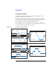
3. (Optional) Set the Additional Pulse fields for the 3-Level Pulse. 3-level pulses
can be achieved by the Primary Pulse and the Additional Pulse. See
Figure 4-16
for examples.
4. On the Load Z Setup window, specify the load impedance of the DUT (device
under test). The value is used to adjust the SPGU output voltage automatically.
The SPGU will output the voltage close to the specified Base or Peak value.
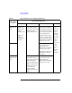
5. (Optional) On the Pulse Switch Setup window, enable the pulse switch, which is
the semiconductor relay mounted in the SPGU output and is used to open the
SPGU channel output. This relay is more durable than mechanical relays, and is
better suited for frequent switching applications.
SW Sync ENABLE (enables the pulse switch) or DISABLE (disables
the pulse switch).
Switching of the pulse switch status (open and close) will be
controlled automatically and synchronized with the output
pulse, as shown in
Figure 4-17.
Delay, Width, and Normal fields will be active when SW Sync=ENABLE.
Delay Delay time from start of pulse output to changeover of pulse
switch. 0 s to Period-100 ns, 10 ns resolution.
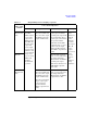
Width Duration to hold the switched state of the pulse switch.
100
ns to Period-Delay ns, 10 ns resolution.
Normal Switch status in the pulse switch normal condition. CLOSE
(normally closes the pulse switch) or OPEN (normally
opens the pulse switch). The pulse switch will change the
status after the Delay-sw time and keep the status until the
Width-sw time elapses, as shown in
Figure 4-17. This
operation is repeated every pulse period.
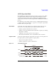
Figure 4-17 Pulse Setup Parameters
Period
Width
V/10
V/10
Leading
Base
Peak
V: Pulse level
Delay
Delay
V/10
V/10
Trailing
Start
Width-sw
Delay-sw
Pulse switch
Normally open
Close
Close
Open
Delay-sw