
User`s guide


Agilent EasyEXPERT User’s Guide Vol. 1, Edition 1 4- 25
Function Details
C-V Sweep Measurement
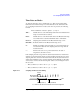
To realize accurate measurements using the four-terminal pair measurement
method, the following connection tips are important. See
Figure 4-13 and Figure
4-14.
• The signal path from MFCMU to DUT must be as short as possible.
• The four-terminal pair configuration must be extended as close as possible to the
DUT.
• The outer shield conductors must be connected together at the extended cable
ends. Then take care of contacts. They must be electrically isolated.
This is the same as connecting the CMU return terminals of the atto sense/switch
unit (ASU) or the guard switch unit (GSWU).
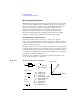
• The signal path from the shield ends to the DUT must be as short as possible.
• If it is possible, make protective guard (plate, shield, or anything) around the
DUT, and connect it to the outer shield conductor of the four-terminal pair
configuration. This minimizes the effects of stray capacitance and electrical
noise. Then take care of contacts. The guard must be electrically isolated.
• The Low (Lcur, Lpot) terminal must be prevented from stray capacitance and
guard capacitance. If the measurement terminal has to be connected to the wafer
chuck, use the High (Hcur, Hpot) terminal to connect to the wafer chuck.
Error Correction
The MFCMU is equipped with the error correction function used to realize accurate
impedance measurements. The correction function minimizes the effects of the error
elements in the extension cables and the DUT interface such as manipulator and
probe card.
• Phase compensation
Corrects phase error caused by extending measurement cables.
• Open correction
Corrects for stray admittance. Effective for high impedance measurements.
• Short correction
Corrects for residual impedance. Effective for low impedance measurements.
• Load correction
Corrects any error by using the working standard.